
nSpec v0.24.2.0 External Release Notes
nSpec Version 0.24.2.0
Release Date:
Documentation Updated:
Major Features: nView Device Viewer, Custom Export File Formats
Overview
nSpec v0.24.2.0. contains some exciting new updates, features, bug fixes, and also important deprecations.
This update includes the ability to write custom formatters for Custom Exporter analyses using newly developed nfmt (nano-format). Additionally, nView now has a Device Viewer, allowing users to look at entire device scans instead of partial tile scans in nView.
Customers with Bonito cameras will see changes to job exposure times due to a measured error between the manufacturer’s reported and actual exposure times, however this will not affect scan times.
Additionally, this version deprecates the use of 0-based indexing for bare wafer and custom scan image tiles, scanned using continuous scanning mode. Previously, bare wafer and custom scans running in continuous scanning mode used 0-based indexing, whereas bare wafer and custom scans running in stop and go mode would use 1-based indexing. This change will ensure that all scans regardless of scan mode will follow the same indexing convention. See v0.24.2.0 Deprecations for more details.
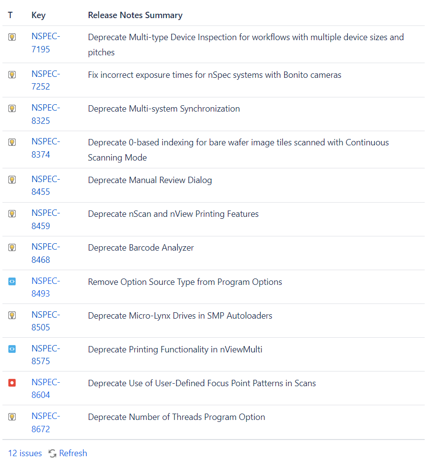
Deprecations
There are a number of deprecations in nSpec v0.24.2.0 to be aware of when upgrading the software.
NSPEC-7195: Deprecate Multi-type Device Inspection for workflows with multiple device sizes and pitches
Previously, multi-type device inspections could be performed for customers with multi-type device samples, in which the devices had different pitches and sizes. Now, users can only perform multi-type device inspections for multi-type device samples that have the same size and pitch. We will implement a workflow to replace the deprecated workflow in the future.
See Multi-Type Device Inspection Workflow for information on the new workflow, also included in the Appendix section.
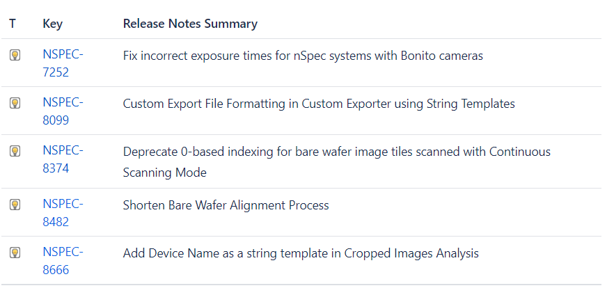
NSPEC-7252: Fix incorrect exposure times for nSpec systems with Bonito cameras
For nSpec systems with Bonito cameras, exposure times will increase for all scans. This is due to a difference found between the manufacturer’s stated exposure times and actual measured exposure times.
All jobs will be automatically adjusted to run at the same speeds as before, so although exposure times will increase on paper by 34 μs for all scans with Bonito cameras, scan times should stay the same.
Part of this automatic adjustment is setting and increasing the value of job property cs-allowable-pixels-motion-blur, which allows users to set the number of allowable pixels of motion blur. For certain contexts, it is acceptable to have more than 1 pixel of motion blur. Setting this property can be used to increase or decrease the stage speed by setting an allowable limit of motion blur.
cs-allowable-pixels-motion-blurcan be set to any value in the range [0.1, 1000.0]. Setting this value less than 1 will decrease stage speed, while setting it to greater than 1 will increase the stage speed. For example, given a scan that is running at 50 mm/s, setting this job property to 4.0 would allow the scan to proceed at 200 mm/s on a stage that supports those speeds. Conversely for a scan running at 200 mm/s, setting this value to 0.25 reduce scan speeds to 50 mm/s.
NSPEC-8374: Deprecate 0-based indexing for bare wafer and custom scan image tiles via Continuous Scanning Mode
Previously, when running bare wafer and custom scans in continuous scanning mode, the first scanned image tile would start at 000. Now, the first image tile index will start at 001. This change was made to match the behavior of both wafer and custom scans running in stop and go mode and device scans, which already use 1-based indexing.
Now all scans will follow the same 1-based indexing convention for naming image tiles across bare wafer, custom, and patterned wafer device scans.
Existing analyses relying on the previous image indexing for bare wafer and custom scans may need to be reconfigured. This will not impact device scans.
For users that wish to continue using the legacy image index, new program option Use Legacy Scan Images Index under Scanning program options can be enabled to restore legacy behavior. Legacy behavior means that bare wafer and custom scans performed with continuous scanning use 0-based indexing, and bare wafer and custom scans performed with stop and go scanning use 1-based indexing for image tiles.
Additionally, when the Use Legacy Scan Images Index option is disabled, all bare wafer scans follow a horizontal scan path. Previously, when running a stop and go scan with the Path Optimization program option enabled under Scanning options, the system would scan in a vertical pattern. The new behavior ensures parity between both scanning modes.
The following table summarizes the indexing scheme and scan paths for bare wafer scans, with the following parameter combinations:
Scan Mode: Continuous Scanning or Stop and Go
Program Option: Path Optimization: Enabled or disabled
Program Option: Legacy Scan Images Index: Enabled or disabled
Scan Type | Scan Mode | Program Option: Path Optimization | Program Option: Legacy Scan Images Index | Scan Path | Indexing Scheme |
|---|---|---|---|---|---|
Bare wafer | Continuous Scanning | Enabled | Enabled | Horizontal | 0 |
Bare wafer | Stop and Go | Enabled | Enabled | Vertical | 1 |
Bare wafer | Continuous Scanning | Disabled | Enabled | Horizontal | 0 |
Bare wafer | Stop and Go | Disabled | Enabled | Horizontal | 1 |
Bare wafer | Continuous Scanning | Enabled | Disabled | Horizontal | 1 |
Bare wafer | Stop and Go | Enabled | Disabled | Horizontal | 1 |
Bare wafer | Continuous Scanning | Disabled | Disabled | Horizontal | 1 |
Bare wafer | Stop and Go | Disabled | Disabled | Horizontal | 1 |
Scan Type | Scan Mode | Program Option: Path Optimization | Program Option: Legacy Scan Images Index | Scan Path | Indexing Scheme |
|---|---|---|---|---|---|
Custom | Continuous Scanning | Enabled | Enabled | Horizontal | 0 |
Custom | Stop and Go | Enabled | Enabled | Random | 1 |
Custom | Continuous Scanning | Disabled | Enabled | Horizontal | 0 |
Custom | Stop and Go | Disabled | Enabled | Horizontal | 1 |
Custom | Continuous Scanning | Enabled | Disabled | Horizontal | 1 |
Custom | Stop and Go | Enabled | Disabled | Random | 1 |
Custom | Continuous Scanning | Disabled | Disabled | Horizontal | 1 |
Custom | Stop and Go | Disabled | Disabled | Horizontal | 1 |
Deprecation Changelog
Major Enhancements
Device Yield Report - Device View
Device Yield Reports now include Device View. Previously, when inspecting devices, users could only view scanned images on a per-tile basis. Now, users can view entire devices at a time when viewing device yield reports in nView.
Overview
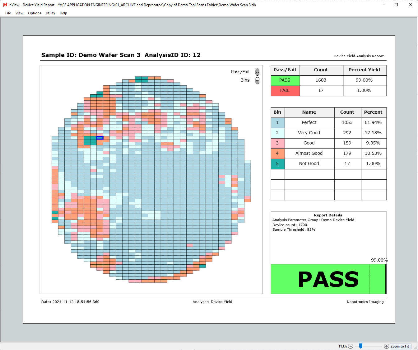
After successfully running Device Yield analysis on a defect-type scan, the analysis results can be viewed in nView. The Device Yield report can be viewed by accessing nView > View > Device Yield Report or Ctrl+ 7.
Device Yield Report Views
The Device Yield report has multiple different views that can be seen by toggling Pass/Fail and Bins, in addition to hovering over individual pass/fail or bin table rows.
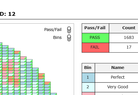
In the next image, both the Pass/Fail and Bins views are turned on.
Each square represents a device, with the color in the top left corner of each device representing the bin associated with the device, and the color in the bottom right corner representing the pass/fail status of the device.

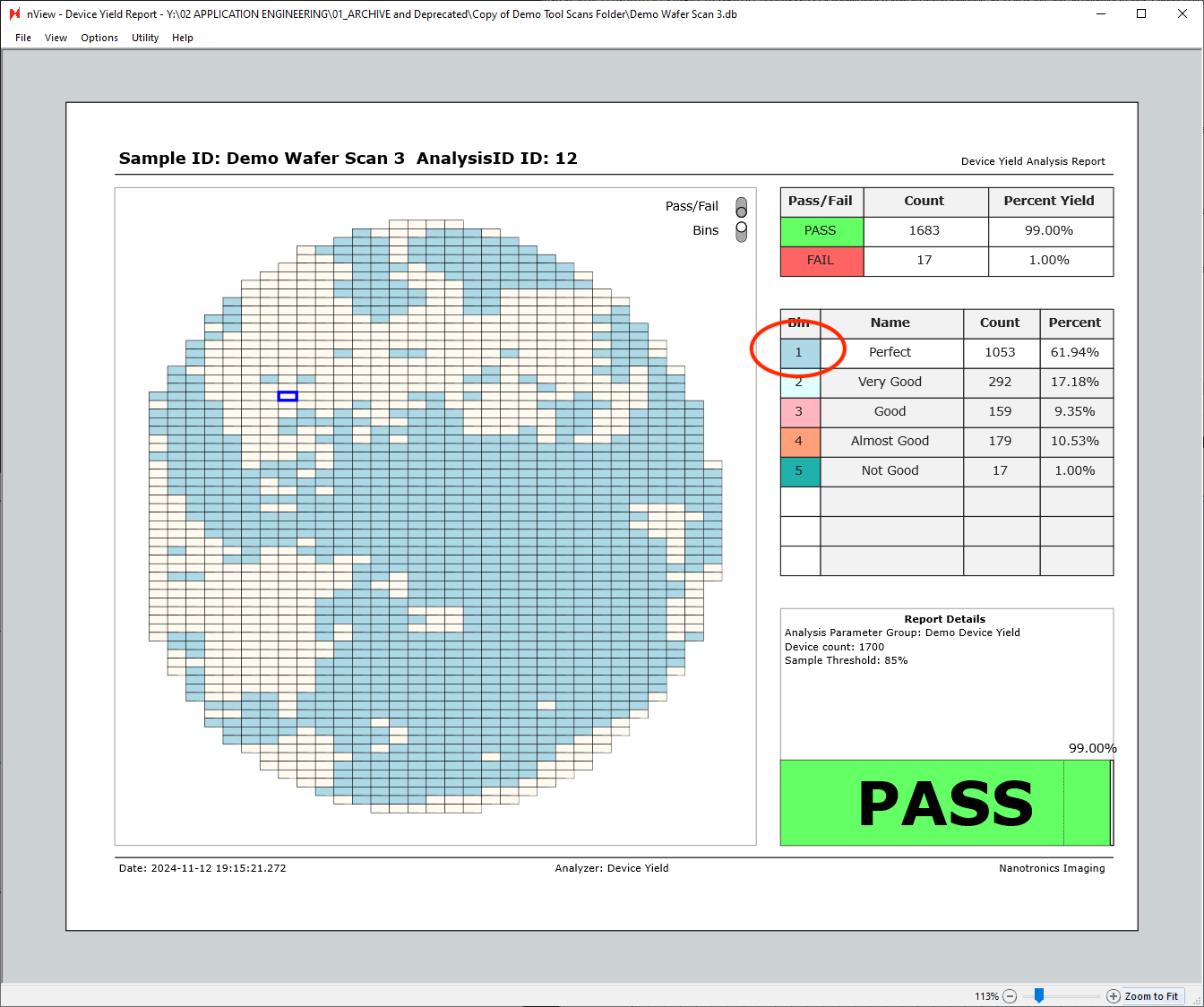
Bins can be toggled off to only show the pass/fail status of each device.

Similarly, Pass/Fail can be toggled off to show the device bins only.
Additionally, hovering over any of the table rows on the right side of the report will highlight the given row’s bin. The view below is with the bins view only enabled, with cursor hovered over the “Bin 1 - Perfect” row.
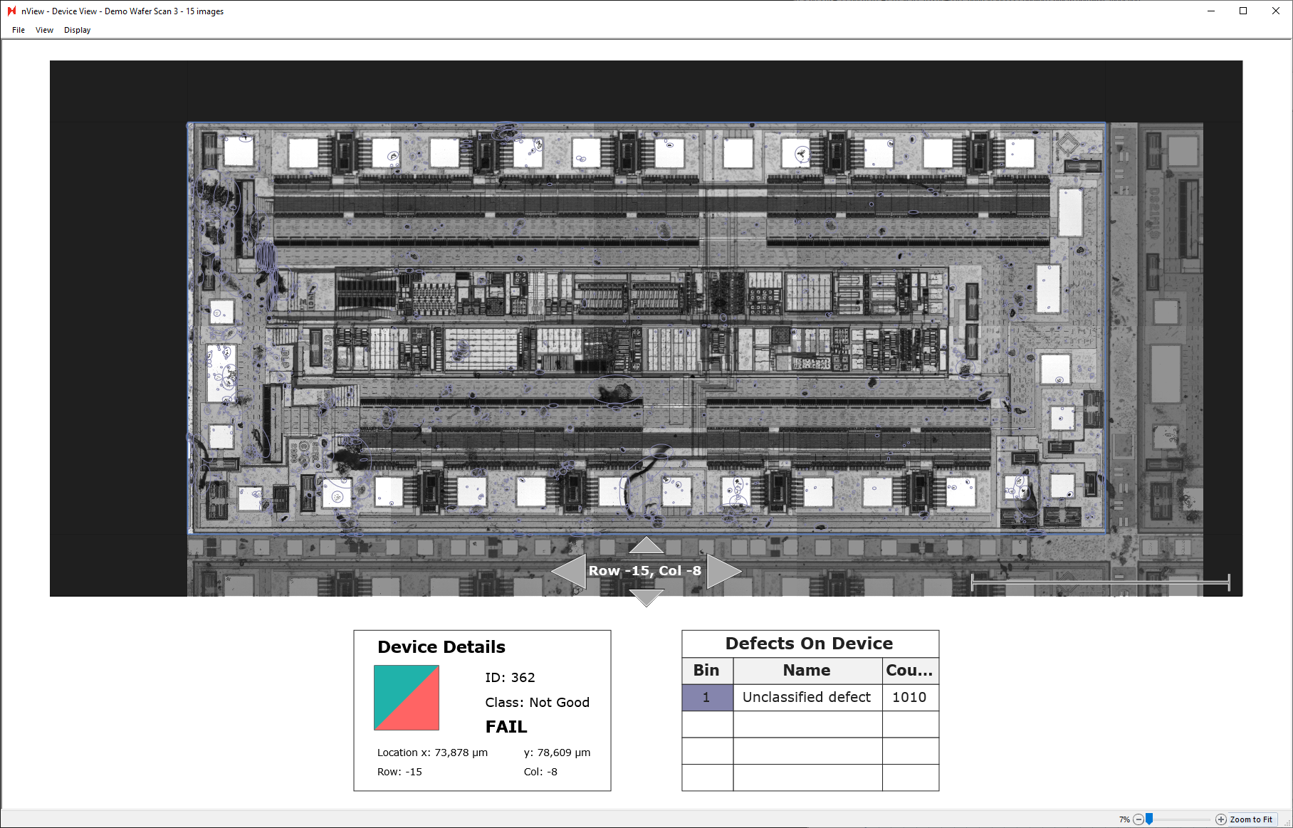
Individual Device View
Individual devices can also be inspected more closely by double-clicking any of the device tiles in the device yield report. Double-clicking a device tile will open a new window of the device view.
Using the up, left, down, right arrows allows you to navigate to view neighboring devices.
Exporting Device Yield Report
Device yield reports can be manually saved and exported directly at nView > File > Save As…
Additionally, they can be exported automatically by placing a Report Summary Image Export after a device yield analysis in an analysis group.
Custom String Template Export File Formatting
Users can create custom export file formatting in Custom Exporter using string templates.
Overview
Users can create custom formatted export files in Custom Exporter using user-defined nfmt (Nano format) files.
This guide assume familiarity with Python f-string formatting. nfmt is an implementation of {fmt} C++ library. We’ve developed a custom syntax-highlighting extension for VS Code to aid in creating nfmt files. Contact support@nanotronics.ai for access to this custom VS extension.
Custom Exporter Usage
To use the custom string template formatter in Custom Exporter, you must select UserDefined as the Export Type.
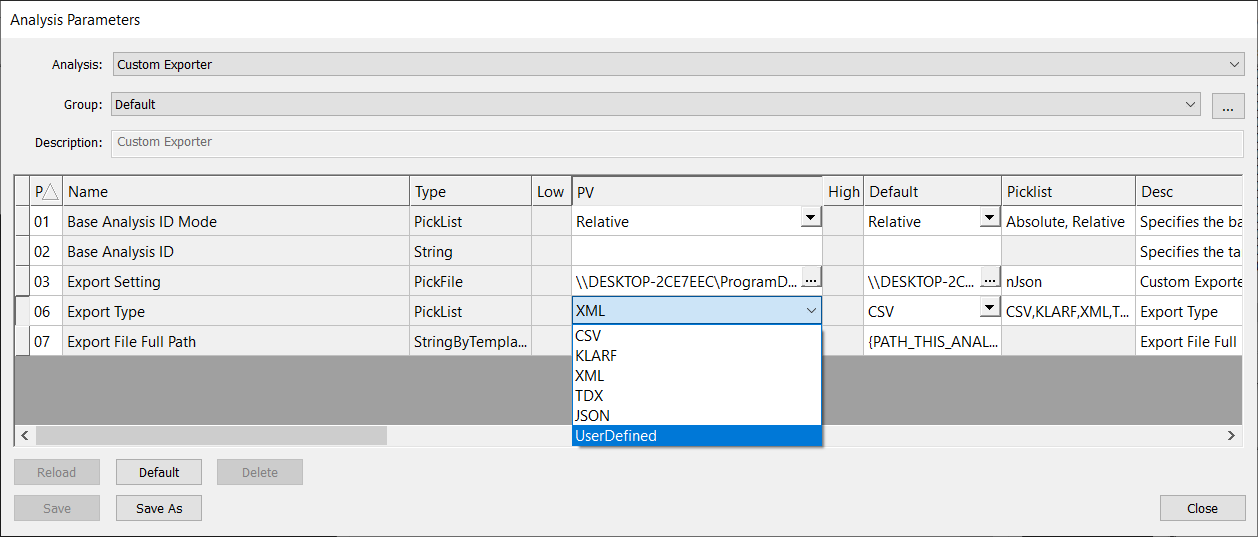
When selecting UserDefined export type, you must provide a nfmt file to format your export. You must point to this nfmt file using the field CustomTypeFile in the Export Setting nJson file.
Below is an example nJson file. Note that the CustomTypeFile is nanofmt.nfmt and the CustomTypeExtension is txt.
{
  "Custom Exporter": {
    "inputTablesNames": "src",
    "CustomTypeExtension": "txt",
    "CustomTypeFile": "nanofmt.nfmt",
    "Views" : [
      {
        "Title": "srcScanID",
        "Query": "SELECT ScanID FROM vwAnalysis WHERE AnalysisID = (SELECT AnalysisID FROM src LIMIT 1)"
      },
      {
        "Title": "vwSrcScan",
        "Query": "SELECT ScanID, Timestamp As StartTime, EndTime, (SELECT COUNT(*) FROM vwImages) AS NumImages , (SELECT PropertyData / 1000 FROM ScanProperties WHERE PropertyName = 'Scan Min X Microns')  AS 'X_mm', (SELECT PropertyData / 1000 FROM ScanProperties WHERE PropertyName = 'Scan Min Y Microns')  AS 'Y_mm', (SELECT PropertyData / 1000 FROM ScanProperties WHERE PropertyName = 'Scan Width Microns')  AS 'Width_mm', (SELECT PropertyData / 1000 FROM ScanProperties WHERE PropertyName = 'Scan Height Microns') AS 'Height_mm', Result, (SELECT PropertyData FROM ScanProperties WHERE PropertyName = 'SampleID') AS SampleName FROM Scans WHERE ScanID = (SELECT ScanID FROM srcScanID)"
      },
      {
        "Title": "vwSrcAnalysis",
        "Query": "SELECT AnalysisID, AnalyzerMenuText AS Analyzer, Timestamp AS StartTime, EndTime, NumDefects, AnalyzerName, Result FROM vwAnalysis WHERE AnalysisID = (SELECT AnalysisID FROM src LIMIT 1)"
      }
    ],
    "Queries": [
      {
        "Title": "scans",
        "Query": "SELECT * FROM Scans"
      }
    ]
  }
}
Example nfmt formatting file
Below is an example nfmt file. Anything not contained in braces { } is considered literal text, and brace characters can be escaped by doubling {{ }}.
Note that within the braces, the nfmt file references and accesses the SQL database queries made in the nJson Export Setting file, e.g. scans and vsSrcScan.
User-Defined Report Sample (from Query)
=======================================
Scans ID : {scans:e{"\t"}:ScanID}
Scans StartTime : {scans:e{"\t"}:Timestamp}
Scans EndTime : {scans:e{"\t"}:EndTime}
Scans Result : {scans:e{"\t"}:Result}
{db:sql{scan, SELECT * FROM vwSrcScan}:e{"\n"}:f{
"
Defined Report Sample (from views)
=======================================
Scan ID : {scan:ScanID}
Scan StartTime : {scan:StartTime}
Scan EndTime : {scan:EndTime}
Number of Images : {scan:NumImages}
X(mm) : {scan:X_mm}
Y(mm) : {scan:Y_mm}
Width(mm) : {scan:Width_mm}
Height(mm) : {scan:Height_mm}
Scan Result : {scan:Result}
SampleName : {scan:SampleName}
{db:
sql{property,
f{"SELECT * FROM ScanProperties WHERE ScanID = {scan:ScanID}"} }
:e{"\n"}
:f{"{property:PropertyName} : {property:PropertyData}"} }
{db:sql{analysis, SELECT * FROM vwAnalysis WHERE AnalysisID = (SELECT AnalysisID
FROM src LIMIT 1)}
:e{"\n"}
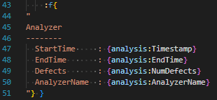
:f{
"
Analyzer
--------
StartTime : {analysis:Timestamp}
EndTime : {analysis:EndTime}
Defects : {analysis:NumDefects}
AnalyzerName : {analysis:AnalyzerName}
"} }
Devices
-------
{db:
sql{device, f{"SELECT * FROM vwDevices WHERE ScanID = {scan:ScanID} ORDER BY
DeviceID"} }
:e{"\n"}
:f{
"
DeviceID : {device:DeviceID}
X : {device:X}
Y : {device:Y}
width : {device:width}
height : {device:height}
Images
------
{db:sql{image, f{"
SELECT * FROM vwImages WHERE ImageID IN
(SELECT ImageID FROM DevicesInImages WHERE DeviceID = {device:DeviceID})
ORDER BY ImageID"} }
:e{"\n"}
:f{
"
ImageID : {image:ImageID}
X : {image:X}
Y : {image:Y}
width : {image:wMicrons}
height : {image:hMicrons}
Defects
-------
DefectID X Y W H Area
{db:sql{d, f{"SELECT * FROM src WHERE ImageID = {image:ImageID} ORDER BY DefectID"}
}
::e{" {d:DefectID:<11} {d:X:<6.5g} {d:Y:<6.5g} {d:W:<6.5g} {d:H:<6.5g}
{d:Area:<9.8g}\n"
} }"
} }"
} }"
} }
Example Export File
The following export file was generated via Custom Exporter using the example nfmt file above. The data is sample data, but typically the data draws from the nSpec scan database. Only a portion of the Defects have been included for brevity.
User-Defined Report Sample (from Query)
=======================================
Scans ID        : 1	2	3	4	5	6
Scans StartTime : 2024-09-08 22:45:10.624	2024-09-08 22:47:04.214	2024-09-08 22:48:05.204	2024-09-08 22:50:10.931	2024-09-08 22:51:09.385	2024-09-08 22:53:06.674
Scans EndTime   : 2024-09-08 22:47:03.977	2024-09-09 12:48:39.323	2024-09-08 22:50:08.973	2024-09-09 12:55:33.344	2024-09-08 22:53:04.566	2024-09-09 13:00:17.962
Scans Result    : Success	Success	Success	Success	Success	Success

Defined Report Sample (from views)
=======================================
Scan ID          : 6
Scan StartTime   : 2024-09-08 22:53:06.674
Scan EndTime     : 2024-09-09 13:00:17.962
Number of Images : 7982
X(mm)            : 15.254580095
Y(mm)            : 15.538067214
Width(mm)        : 310.29911172
Height(mm)       : 310.501818577
Scan Result      : Success
SampleName       : 300mm_Wafer
Alignment Angle : 0.789400
Alignment File : \\DESKTOP\Alignments\300mm_Wafer_Alignment.csv
Autofocus Set : 300mm_Wafer_AF
Autofocus Type : Automatic Predictive
Autoloader Set : None
CenterX : 170384.977373
CenterY : 170668.930430
DiePitchX : 64498.265301
DiePitchY : 90001.686035
Edge Exclude : 3000.000000
Exposure Time : 1
Filter Slider Status : None
FlatOffsetAngle : 0.000000
FlatSegmentLength : 0.000000
Focus Point Pattern : 300mm 9 Point
Focus Predictor : PreFoc Polynomial Standard
Golden Tile Number of Devices : 8
Golden Tile Scan : 1
Golden Tile Tiles per Device : 88
Illumination : Bright Field
Image Height Microns : 7410.389169
Image Height Pixels : 4268
Image Width Microns : 7888.396686
Image Width Pixels : 4398
Initiator : Manual
Install Build Version : 0.24.2.0
JobName : 300mm_Wafer_Demo_Job
JobUpdateTime : 2024-09-08 23:42:31.428
KLARFMode : 1
Layout File : D:\Scans\300mm_Wafer\Scan_006\Layout.csv
Light Intensity Control 1 : Setpoint
Light Intensity Control 2 : Setpoint
Light Intensity Control Value 1 : 0
Light Intensity Control Value 2 : 1000
Light Source 1 : Nano:Transmitted
Light Source 2 : Nano:Reflected
Mosaic Name : 300mm_Wafer_Mosaic.png
Objective : 2.5X - CFI L Plan 2.5X
OriginOffsetX : 0.000000
OriginOffsetY : 0.000000
Pattern : WholeStage
Pattern Type : 2
Radius : 149988.238372
SampleCenterX : 172401.665016
SampleCenterY : 172685.624342
SampleID : 300mm_Wafer
SampleLength : 300.000000
Scan Height Microns : 309401.818577
Scan Min X Microns : 16256.183319
Scan Min Y Microns : 16348.184435
Scan Tilt Angle : 0.000000
Scan Width Microns : 308409.111720
Stage Height Microns : 343179.700000
Stage Width Microns : 344681.400000
XOffset : -17537.000000
YOffset : -18344.000000

Analyzer
--------
  StartTime     : 2024-09-09 17:20:57.937
  EndTime       : 2024-09-09 17:21:31.650
  Defects       : 23189
  AnalyzerName  : nrad_rangeselect

Devices
-------
  DeviceID : 1
  X        : 28645.193836
  Y        : 117102.611014
  width    : 63391.820591
  height   : 77005.699667

  Images
  ------
  ImageID  : 2001
    X      : 28642.416191
    Y      : 117095.278032
    width  : 4461
    height : 4169

    Defects
    -------
      DefectID    X      Y      W      H      Area

  ImageID  : 2002
    X      : 36569.712877
    Y      : 117096.278032
    width  : 4461
    height : 4169

    Defects
    -------
      DefectID    X      Y      W      H      Area

  ImageID  : 2003
    X      : 44498.009564
    Y      : 117096.278032
    width  : 4461
    height : 4169

    Defects
    -------
      DefectID    X      Y      W      H      Area

ImageID  : 5750
    X      : 138607.349836
    Y      : 82548.104671
    width  : 4461
    height : 4169

    Defects
    -------
      DefectID    X      Y      W      H      Area
      97734       2134.8 2252.4 5.6254 3.9378 22.468003
      97735       1714.6 2124.7 6.0588 3.3427 20.88575
      97736       534.98 2172.5 166.51 102.38 9194.793
      97737       895    2134.8 32.057 1.636  24.050257
      97738       2349.7 2105   7.5578 8.3532 54.429529
      97739       547.35 2070.7 4.7733 4.7733 21.518651
      97740       895    2040.9 1.1251 37.127 24.050257
      97741       534.98 2045.9 166.51 93.381 6940.3979
      97742       1630.8 1974.5 1.1251 50.628 23.100905
      97743       296.46 1921.1 7.16   11.933 74.365926
      97744       895    1911.5 1.1251 50.628 35.126033
      97745       534.41 1919.4 165.95 101.82 9144.4774
      97746       895    1845.1 1.1251 57.941 33.54378
      97747       232.89 1797.9 5.0629 6.1879 31.328624
      97748       1630.8 1856.4 1.1251 125.45 58.543389
      97749       534.41 1793.4 165.95 92.819 9597.6348
      97750       2462.8 1754.6 24.263 9.5844 164.23794
Basic Pieces of Syntax
We only add new syntax to the {fmt} library for format-specifiers; these are the parts of a {variable_name:format_spec} to the right of the first colon. There are a couple of basic ideas:
Joining format-specifiers
Instead of using a single block of characters from a : to a } to denote how to format some typed thing, we will allow a sequence of these to iteratively turn the thing into progressively easier-to-format things. This is not required in regular f-strings, which never permit a : to appear in a format-specifier.
Iterables
If you have some iterable variable containing things of type T, then it is formatted with a joiner to become something that is formatted with a format-specifier for something of type T. So for example, if we had scan_ids,was a list {1, 2, 3}, and it was formatted with {scan_ids:, :03}, that would produce the string 001, 002, 003.
Note that this is not quite the same as the range-based syntax extension described in the library, because we can add joiners.
Function calls
In some places, we embed something that should be read as a function call. Function calls are a name matching [A-Za-z_][A-Za-z_0-9]*, followed by a {}-wrapped, ,-delimited sequence of arguments. Whitespace before and after is ignored. For example:

Would require foo and bar to be variables in the surrounding context, foo to understand how to find a function bar, and implicitly that function must return a floating point number to be correctly formatted by the regular format specifier:<6.5g.
Escaped f-strings
Anywhere in a format specifier that requires a string, we can recursively have an f-string. This is done with the reserved functions f and e. The basic syntax for this is to wrap in "" and {}:
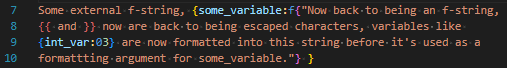
Note, critically, the space after the magenta-highlighted }. Some trailing whitespace after this function call is mandatory for distinguishing closing two scopes and intending to embed a raw } into the embedded f-string.
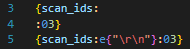
The function e has the same semantics, but additionally unescapes C-style \<char> characters. The main ones of use are \t, \r, \n, \0 (tab, carriage return, line feed, null). All but a null can technically be embedded in a string without escaping, but they can be hard to read. The following two lines express the same intent, but the latter is much clearer:
For these embeddede and fstrings, whitespace between the { and " and " and } can be freely added. If whitespace between the { and " matches exactly with whitespace at the beginning or end of the quoted string, it is removed; this allows for clean syntax separating the management of a block of text to be embedded and the text to be embedded. For example:
Embeds an f-string which starts with A and ends immediately after the AnalyzerName, without any trailing newline (for now, don’t worry about what theanalysis variable is).
SQL formatting
Formatting a DB
For now, a SqlDB exposes exactly one callable function, sql{row_name, sql_string}, which runs the query in sql_string and returns an iterable of rows, each of which will be exposed to subsequent formatting as a variable named row_name. For now, this means that to produce anything useful, the row must be formatted with some embedded f-string, since it is named.
Currently we are in the context of file exports for an analysis, there’s only one natural DB (the scanDB), which is exposed as a variable named db. As in other Exporters, the .njson file may have a number of queries to produce named views or other iterable rows that were returned by a SQL query.
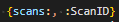
Formatting a SQL row
Rows are dictionaries, indexed by their column titles. So something like:

Will produce a list of the ScanIDs for every scan in the Scans table, separated with", ".
If a query is embedded in the .njson file, e.g. as
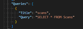
then the entire iterable of results will be named scans, and so can be formatted like:
This is structurally less flexible, but is simpler syntax in the .nfmtfile.
Note that in either case, the format specifier here is simply producing some integer that is then default formatted; if this needed to be controlled with a further specifier for width or padding that occurs exactly as for any other integer.
New Features
Highlights
NSPEC-7252 Fix incorrect exposure times for nSpec systems with Bonito cameras
For nSpec systems with Bonito cameras, exposure times will increase for all scans. This is due to a difference found between the manufacturer’s stated exposure times and actual measured exposure times. All jobs will be automatically adjusted to run at the same speeds as before, so although exposure times will increase, scan times should stay the same. See v0.24.2.0 Deprecations for more on this change.
NSPEC-8099 Custom Export File Formatting in Custom Exporter using String Templates
Users can now fully customize export file formats using user-defined nfrmt files using Custom Exporter. See the Major Enhancements section of release notes for more information on how to create and use custom formatters.
NSPEC-8374: Deprecate 0-based indexing for bare wafer image tiles scanned via Continuous Scanning Mode
See v0.24.2.0 Deprecations for more on this change, which affects the naming convention for image tiles scanned via bare wafer continuous scans.
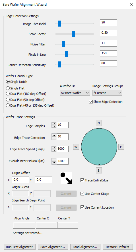
NSPEC-8482 Shorten Bare Wafer Alignment Process
There is a new option in the Bare Wafer Alignment Wizard to Trace Entire Edge of the sample when performing alignment. By default, this behavior is enabled. This matches the legacy behavior of bare ware alignment.
If you would like to use new improvements that reduce the speed of bare wafer alignment by 2-3x, uncheck the Trace Entire Edge box. Note that this new improvement assumes that the camera is already directed at the sample, and that the sample has not been manually loaded on the far ends of the stage.
NSPEC-8666 Add Device Name as a string template in Cropped Images analysis
Defect device names can be used to name export files in Cropped Images analysis using string template {DEFECT_DEVICE_NAME}.
New Features Changelog
Bug Fixes
Highlights
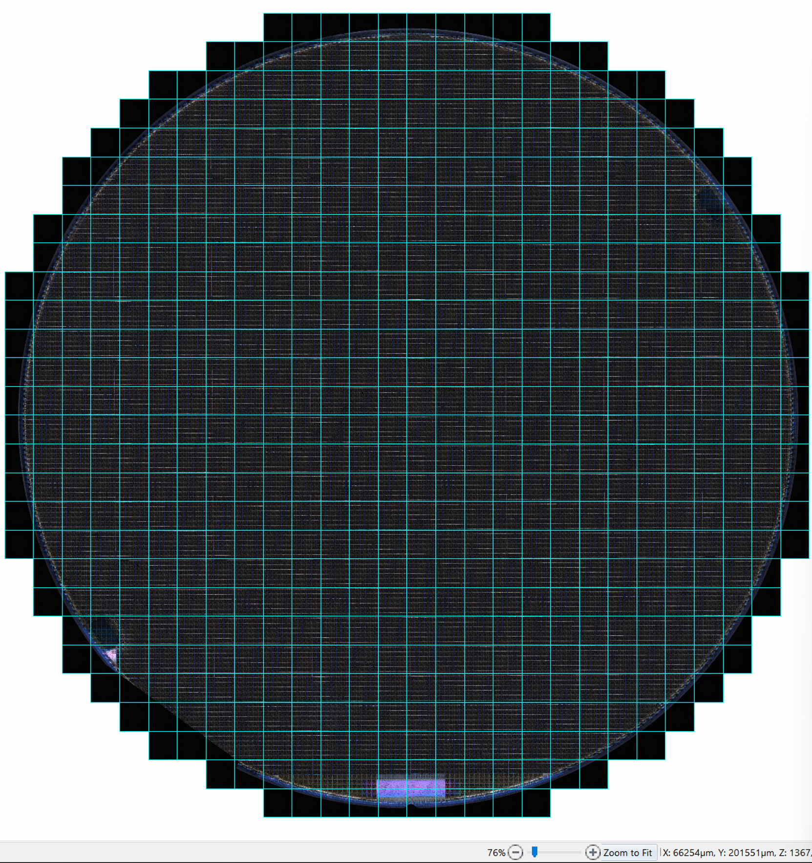
NSPEC-7685 Cannot scan 8 inch wafer at 1.25x
Previously, users had difficulty scanning larger wafers at low magnification objectives. Now, users can enter a positive X and Y offset when inputting a wafer-type pattern in order to capture the entire wafer in a scan using a low magnification objective.
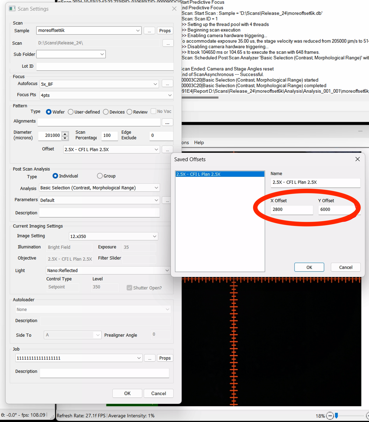
The resulting scan encompasses all edges of the wafer.
NSPEC-8708 Suffix always appended to Cropped Images stacked TIFF export files
When running Cropped Images analysis with parameter Export Many Images As Single File set to TRUE, every export file has the suffix.tiffCroppedDefects.tiff appended to the file name.
Changelog
Appendix
Multi-Type Device Inspection Workflow
Overview
nSpec supports scanning patterned wafers with multiple device types in a single scan. This article will walk through how to create a multi-device layout using the Create Device Layout dialog.
Note that in this workflow, the devices must be the same shape and size, otherwise, users with samples with devices of different sizes will need to run a scan and create a unique device layout for each device type.
Prerequisites
Prior to creating any device layout, you must create in the following order:
Image settings group
Autofocus group
North-south-origin alignment
Layout Creation
After creating and gathering all prerequisites, navigate to nScan - Stage View > Scan > Create Device Layout.
For general guidance on creating a device layout, see Create Device Layout. We recommend reading this article first before continuing this guide if you have never created a device layout before.
Create a layout as you would with a single type device layout, measuring the die and pitch and generating a layout using either rectangular or circular extrapolation.
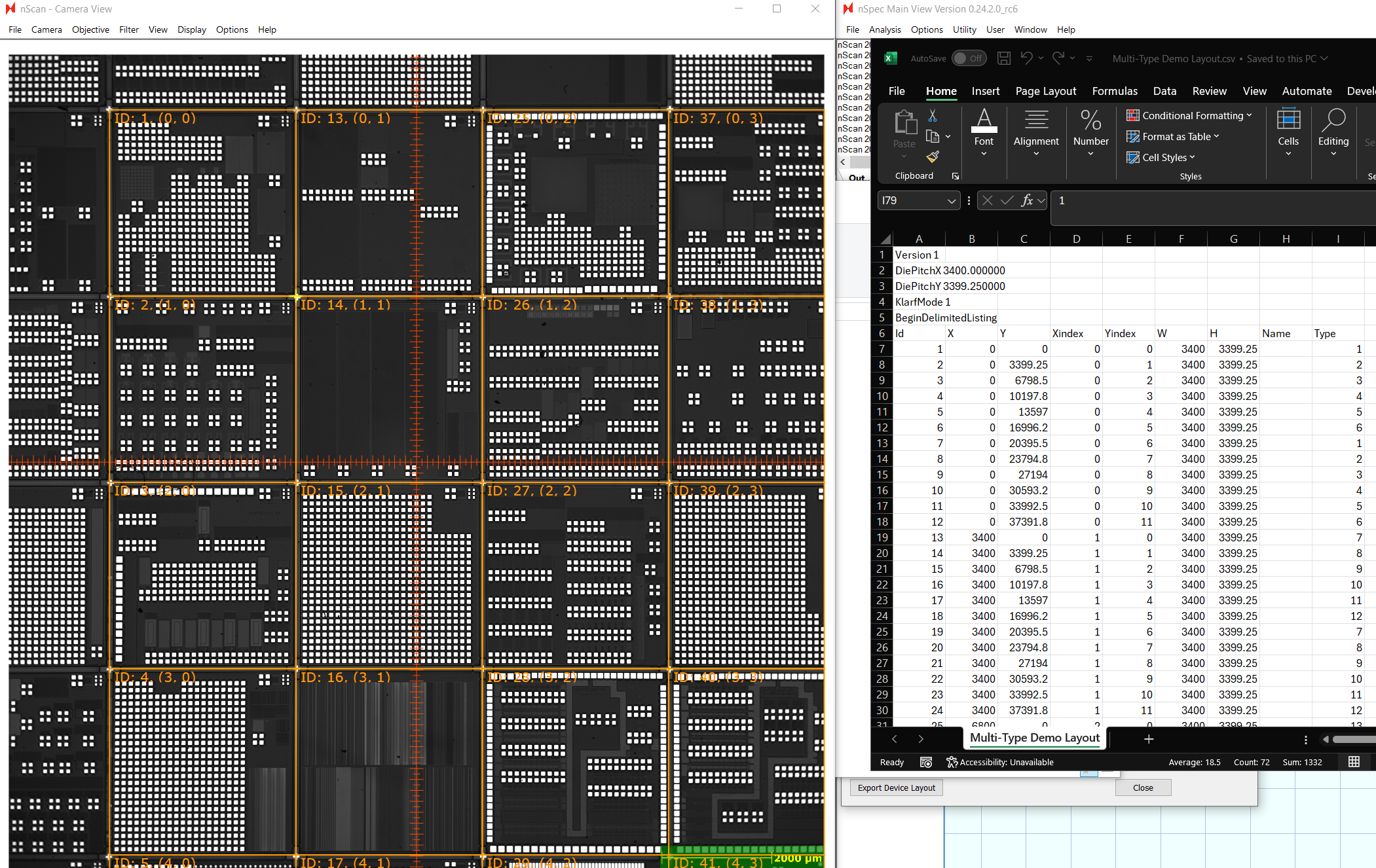
When finished, Export Device Layout, then open the resulting CSV file.
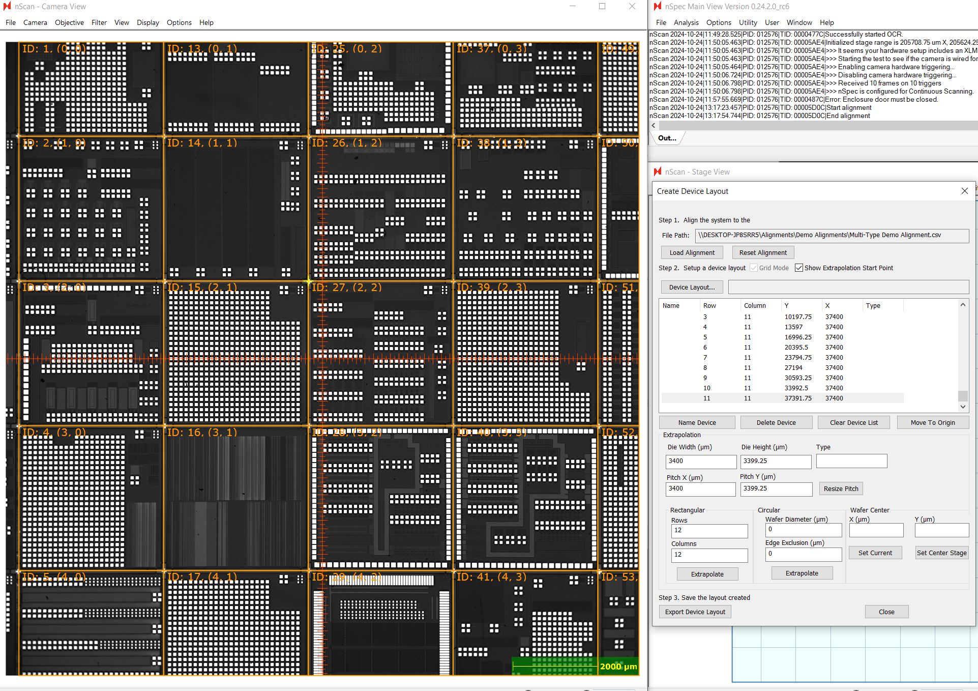
Create a column named “Type”. Assign each device to a number representing its device type. We recommend using a 1-based index for type. In this example, there are 36 different types of devices, so we will use 1-36 to indicate the 36 device types.
The X, Y columns represent the location of each device on the stage relative to the origin selected in the alignment file. The Xindex and Yindex represent the device’s position in units of devices, also relative to the origin. The Xindex and Yindex of each device can be seen in the nScan - Camera View.
Scan Setup
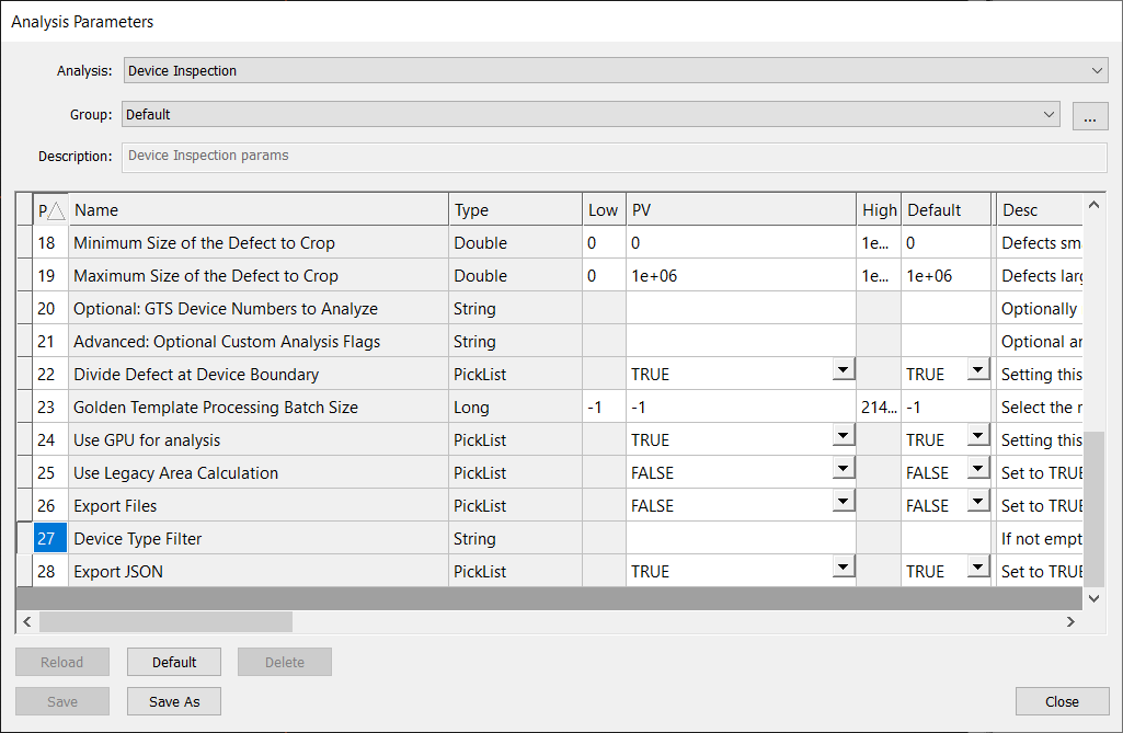
The last step is setup the device inspection scan. Setting up a multi-type device scan is almost identical to the procedure described in Device Inspection Analysis, with some small changes.
First, all devices types will be scanned and analyzed, unless using the Device Type Filter parameter for Device Inspection.
If you’d like to analyze just a subset of device types, you can input a regular expression in the Device Type Filter to indicate which types should be analyzed. The regular expressions should follow ECMA-262 regex patterns. For example, ([1-9]|1[0-8]) would analyze device types 1-18.
Note, that you cannot use both the Device Type Filter and Optional: GTS Device Numbers to Analyze parameters. Using both will cause the analysis to fail.
Previously, Optional: GTS Device Numbers to Analyze enabled a more difficult multi-type device workflow which required users to enter in every device ID to be analyzed, instead of using types.