
nSpec v0.22.1.0 External Release Notes
nSpec Version 0.22.1.0
Release Date:
Documentation Updated:
Major Features: Custom Reporting & Exporting, High Resolution Mosaics
Overview
Introducing nSpec v0.22.1.0! This release is packed with some powerful new functionality that we’re excited to see running in the field, including:
High Resolution Stitched Mosaic Generation
Custom Reporter - a dynamic new tool for embedding data wrangling scripts into production recipes
Custom Exporter - a highly configurable tool for generating analysis result exports with the exact data you need
Live View Enhancements - pausing, informational banner with live intensity, FPS readings, and more
Option to Skip Pre-alignment - For optimally fast wafer handling
In combination, these new tools allow nSpec to support almost any application demand, no matter how niche, with a little assistance from our Applications Engineering team.
Upgrading to v0.22.1.0
Required Library Update!
To upgrade from previous versions, a few things need to be checked:
Run all upgrading steps for versions v0.21.0.0, v0.21.1.0, and v0.22.0.0 - we recommend running all installers for major builds of nSpec between the previous version and the target version.
Run the nanotronics-libraries-installer-v22_1-20220321 installer to update 3rd party libraries related to the new software build. Contact technical service if you are missing this installer.
nJson format has been updated compared to v0.22.0.0, resulting in a breaking change for customers using the Dislocation Analyzer if configured for that version
Important for any customers using the Dislocation Analyzer: The structure of the Dislocation Analyzer nJson file changed between versions v0.22.0.0 and v0.22.1.0
Conversion Instructions: To convert the old format to the new format, move all root-level fields except for “parameters” into an object that is assigned to the new field “Dislocation”
Old nJson format:
{
   "parameters": [
      ...
    ],
    "classifications": ...,
    "otherClass": ...,
    "chainClass": ...,
    ...
}
New nJson Format:
{
   "parameters": [
      ...
    ],
    "Dislocation": {
      "classifications": ...,
      "otherClass": ...,
      "chainClass": ...,
      ...
    }
}
Major Enhancements
Custom Reporter
Overview
Custom Reporter makes it possible to build highly customizable and consolidated reports using one or more previously run analysis results. This can be used in a myriad of ways to meet specific customer needs. Importantly, this has been implemented in a manner that is generic, so this will work for all defect-type analysis results across nSpec. Custom Reporter opens up many possibilities.
Here are a few use case examples:
Combine Device Inspection & AI Analysis reports so that you can remove nuisance defects one either analysis, while also creating a report that has defect class information and pixel-accurate area.
Combine multi-type Device Inspection analysis into a single report for easier defect review.
Combine AI and Basic Selection Analyses Results for pixel-accurate Area reporting.
How Does it Work?
The Custom Reporter generates a new analysis entry in the image database, generated via an embedded SQL query. This Query must generate data that can be saved into the Defects table in the scan database. Therefore, in order to generate fully supported reports within nSpec, the query must output a set of defects where each defect has all the following columns of information:
Column Name | Data Type |
|---|---|
DefectID | INTEGER |
ImageID | INTEGER |
AnalysisID | INTEGER |
DeviceID | INTEGER |
X | REAL |
Y | REAL |
W | REAL |
H | REAL |
Area | REAL |
Eccentricity | REAL |
Orientation | REAL |
XinDevice | REAL |
YinDevice | REAL |
ClassID | INTEGER |
Score | REAL |
Contour | TEXT |
ClassName | VARCHAR |
Note: Contour can be an empty string, andClassName is optional and can be used to output defect classes within the SQL script. If ClassName is written, nView will allow users to view the Class Report when reviewing results.
The Custom Reporter is a tool to access the database, NOT to modify the database. Applications/Tech Services Engineers and customers do not have the right to modify the database. No query should attempt to create or delete data.
Custom Reporter Analysis Parameters
Custom Reporter, like Custom Exporter, was built with the intention that an internal Nanotronics Applications Engineer or Technical Service Engineer would assist customers by configuring an nJson file for custom applications. Then users are able to point at these nJson files within the parameters for the Custom Reporter, by populating the Report Setting field:
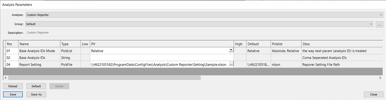
Param Name | Options | Description |
|---|---|---|
Base Analysis IDs Mode | Absolute, Relative |
See Post-Analysis Referencing section (Link) |
Base Analysis IDs |
|
See Post-Analysis Referencing section (Link) |
Report Setting |
| Select a nJson file of the import setting. |
Referencing Prior Analyses
For guidance on how to set up post-analysis referencing, visit the appendix page for Post-Analysis Referencing
Configuring the nJson File
The nJson file must be written and configured by Nanotronics Technical Service or Applications Engineers. To request a new custom reporting application that may require assistance, please contact support@nanotronics.ai to request support.
Custom Exporter
Overview
The Custom Exporter allows users to build highly customizable exports that report on all the desired defect information collected during any previously-run analysis. Like other analyses like the Custom Reporter and Dislocation Analyzer, the Custom Exporter requires an nJson file loaded with relevant SQL scripts.
Configuring the nJson File
The nJson file must be written and configured by Nanotronics Technical Service or Applications Engineers. To request a new custom reporting application that may require assistance, please contact support@nanotronics.ai to request support.
Core Features
CSV column headers are completely configurable. No matter what nSpec calls a defect attribute, users have the ability to rename them to align with the customer vernacular. For example, within nSpec databases we might refer to defect width as “W”, but in this export we can rename that to “width” or “defectWidth”, or anything else that is required for smooth integration with the user’s application.
Embedding math and custom calculations
In addition to simply exporting columns directly, the Custom Exporter will allow us to perform any operation that is legal within SQL code. This gives enormous flexibility in reporting exactly what is needed.
For more information on embedded calculations via the custom exporter, please contact the applications team.
Parameters

Param Name | Options |
|
|---|---|---|
Base Analysis IDs Mode | Absolute, Relative | See Post-Analysis Referencing for more information and usage. |
Base Analysis IDs |
| See Post-Analysis Referencing for more information and usage. |
Export Setting |
| Select a nJson file of the Report setting If you have a new request for a new functionality, please request support from support@nanotronics.ai |
Export Type | CSV, KLARF, XML, TDX, JSON, UserDefined | Export file format. See Custom Export File Formatting with String Templates if you choose to created a custom UserDefined file export. |
Export File Full Path |
| Dynamically name export files with string templates. See Export File Full Path Parameter for more information and usage. |
[DEPRECATED] Custom Filename Suffix | Optional | Deprecated with introduction of Export File Full Path parameter. If non-empty, this suffix will be directly added to filename. If using nSpec v0.23.1.0 or earlier, the suffix will be added following an underscore. |
High Resolution Mosaics
Overview
Currently, the post-scan mosaic generated by nSpec is a low resolution copy of what appears on the nSpec - Stage View after a scan. The High Resolution Mosaic Generator (HRMG) allows users to generate flawless, perfectly stitched, and up to full resolution mosaics matching the input scan pixel resolution.
The most common use cases for HRMG are:
Saving a single high quality continuous image of wafer samples for manual defect inspection
Removing gaps between image tiles caused by optical aberration
Generating image sets for the Virtual Device Inspection (VDI) workflow
The High Resolution Mosaic Generator is disabled by default. If you would like to use this feature and it is not currently enabled, reach out to mailto:support@nanotronics.ai for assistance to activate.
Usage
The HRMG is highly flexible, and accepts an overlapped nSpec scan, then outputs a mosaic or image set depending on the runtime configuration. The most basic output generates a full-resolution mosaic of a wafer scan without any image registration. In this scenario, the algorithm simply positions the input image tiles adjacent to each other. Inputting an overlapped scan to the HRMG is more useful, as the HRMG will perform stitching registration calculations between all of the image tiles. This means there will be no discontinuities across the high resolution image output, under nominal input conditions.
The job property percentOverlap can be assigned to any job to produce an overlapped scan. For the HRMG, a value of 15% is recommended.
The following matrix describes supported input scan types:
Scan Type | Requires Device Layout | Output | Supported? |
|---|---|---|---|
Wafer | - | High-res Image | Yes |
Aligned Wafer | - | High-res Image | Yes |
Aligned Wafer | Yes | Device Scan* (VDI Workflow) | Yes |
Device | Yes | High-res Image | Yes |
User-Defined | - | High-Res Image | No |
*Notice that if the input wafer is aligned and a device layout is provided as an input to the HRMG parameters, the output is not a single mosaic image but rather a Device Type Scan. This is called the Virtual Device Inspection workflow, and is a sepa
Parameters
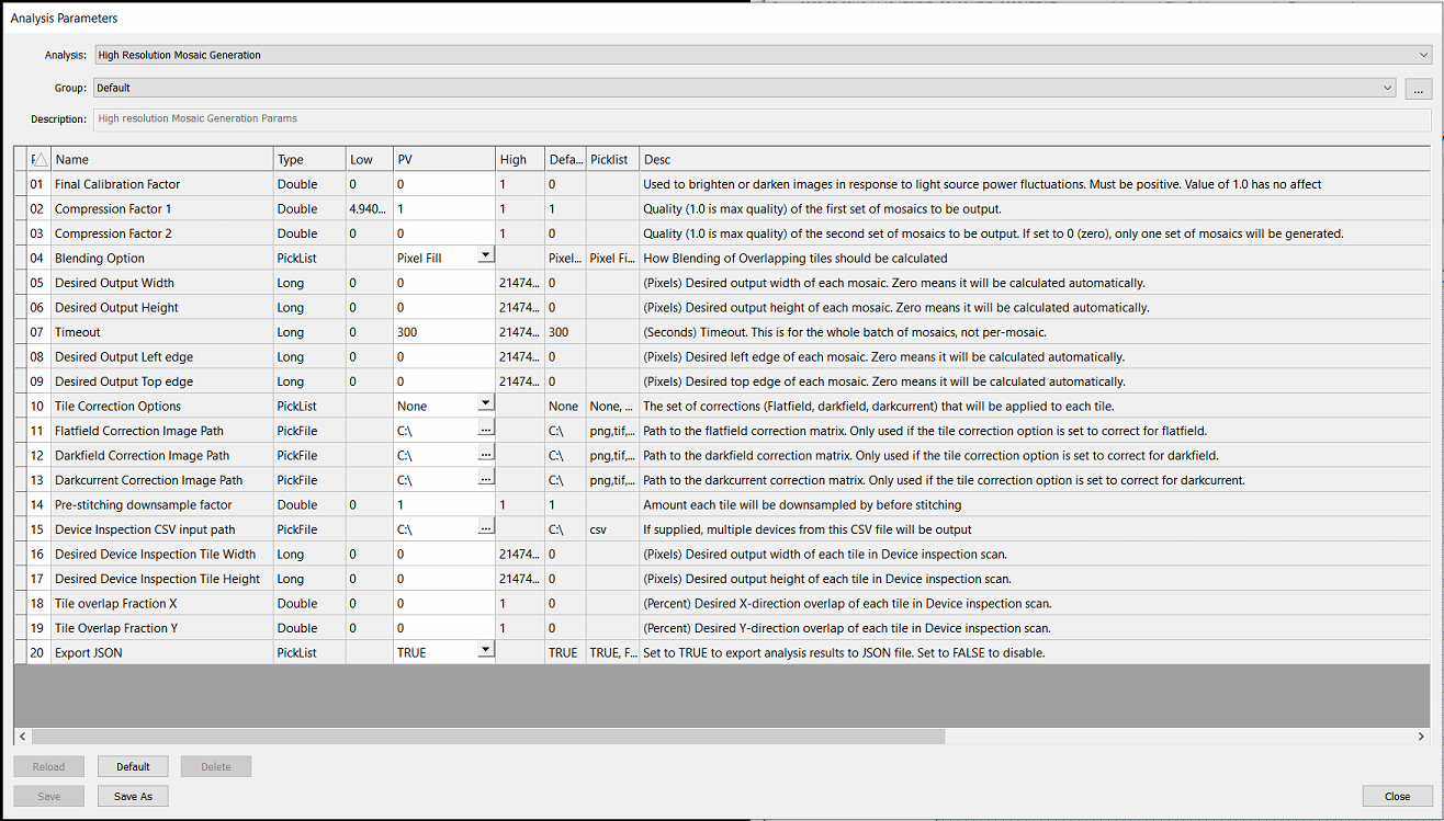
There are many parameters for this analysis, but for the most part these can be left as default values. The table below provides descriptions and notes on the HRMG parameters.
Parameter | Description | Note |
|---|---|---|
Final Calibration Factor | Used to brighten or darken images in response to light source power fluctuations. Must be positive. Value of 1.0 has no affect | Recommend ignoring this parameter unless instructed by Technical Service team. This parameter interacts with other features. |
Compression Factor 1 | Quality (1.0 is max quality) of the first set of mosaics to be output. |
Important! High Resolution Mosaics can only save to disk if small enough to comply with Windows and TIF image format constraints. Compression must be small enough to generate an image < 4GB If the mosaic is larger than this, the Mosaic Generator will silently fail and reports as complete in the exception log even though no mosaic is output |
Compression Factor 2 | Quality (1.0 is max quality) of the second set of mosaics to be output. If set to 0 (zero), only one set of mosaics will be generated. | |
Blending Option | How Blending of Overlapping tiles should be calculated (Pixel Fill, Gradient Mask) | For smoother blends, Gradient Mask is recommended. |
Desired Output Width | (Pixels) Desired output width of each mosaic. Zero means it will be calculated automatically. | Setting this will override compression factors. |
Desired Output Height | (Pixels) Desired output height of each mosaic. Zero means it will be calculated automatically. | Setting this will override compression factors. |
Timeout | (Seconds) Timeout. This is for the whole batch of mosaics, not per-mosaic. | |
Desired Output Left edge | (Pixels) Desired left edge of each mosaic. Zero means it will be calculated automatically. | Recommend setting to 0. |
Desired Output Top edge | (Pixels) Desired top edge of each mosaic. Zero means it will be calculated automatically. | Recommend setting to 0. |
Tile Correction Options | The set of corrections (Flatfield, darkfield, darkcurrent) that will be applied to each tile. | Recommend setting to None and using global system flatfield correction (FFC). |
Flatfield Correction Image Path | Path to the flatfield correction matrix. Only used if the tile correction option is set to correct for flatfield. | See above |
Darkfield Correction Image Path | Path to the darkfield correction matrix. Only used if the tile correction option is set to correct for darkfield. | See above |
Darkcurrent Correction Image Path | Path to the darkcurrent correction matrix. Only used if the tile correction option is set to correct for darkcurrent. | See above |
Pre-stitching downsample factor | Amount each tile will be downsampled by before stitching | Recommend stitching at full resolution (1.0) |
Device Inspection CSV input path | If supplied, multiple devices from this CSV file will be output | *See Virtual Device Inspection workflow for details on this format |
Desired Device Inspection Tile Width | (Pixels) Desired output width of each tile in Device inspection scan. | Recommend outputting image tiles that match the input tile width (ex: 4096px by 4096px for systems with a Bonito Camera with standard configuration |
Desired Device Inspection Tile Height | (Pixels) Desired output height of each tile in Device inspection scan. | See above |
Tile overlap Fraction X | (Percent) Desired X-direction overlap of each tile in Device inspection scan. | Recommend setting to 0 |
Tile Overlap Fraction Y | (Percent) Desired Y-direction overlap of each tile in Device inspection scan. | Recommend setting to 0 |
Export JSON | Set to TRUE to export analysis results to JSON file. Set to FALSE to disable. |
New Features
Highlights
NSPEC-5501: Pixel Intensity for Field of View in Live View
At the bottom left of the Live View, an informational ribbon now includes some information about the Live View such as Refresh Rate, and Average Intensity. Average Intensity is reported as a percentage from 0-100%, where 0 represents a fully dark image, and 100% represents a totally white or bright image.
To report on average image intensity of a specific Region of Interest within the live view, use Ctrl-Left Click to drag and define a Region of Interest. While this selection is active, only this region of interest will be sampled and reported for intensity.
This feature could be helpful for tuning optimal Image Settings for different recipes, to verify that specific ROIs within a device are not over-saturated.
NSPEC-6039: Pausing Live View
Even best efforts to ensure a vibration-free environment for inspection cannot completely eradicate ambient vibrations. These vibrations can be especially visible when working with very high magnification objectives (ex: 20x, 50x, 100x). We have added an ability to pause the live view, which makes it so much easier to perform Critical Dimension Measurements without having to deal with shaking images.
When paused, an orange-red border appears on Live View and a “Pause” icon ⏸ appears in the upper left corner of the display.
There are two ways to pause the live view:
On the keyboard, click the
PauseorPause/BreakbuttonRight click the Live View window to open the context menu, and select “Pause Live View”.
While paused, clicking the Live View display will no longer move the stage to the clicked position.
NSPEC-6057: Option to Skip Prealigner During Wafer Loading
There are some use cases where pre-alignment is not a necessary step in the wafer loading process. This feature provides an option to completely skip the pre-alignment station when loading wafers. This option can reduce total cassette scan-time by about 40 seconds.
To set this up, open the Autoloader Calibration dialog. For the alignment algorithm, select “None” - that’s it!
NSPEC-5624: Remove Translations from the Codebase
Translations were added to nSpec in a way that wasn’t able to scale as new features were developed. An audit of our translations throughout nSpec revealed they were in a sad state and were full of inaccurate or missing translations. Translations will be reintroduced someday again soon in a way that actually help non English language speakers get the most out of nSpec.
New Features Changelog
Bug Fixes
Highlights
NSPEC-5911: nView resizing button doesn't expand to fit entire multi-tile Field of View
Previously, at the lower right corner of nView’s image tile window, if you clicked on the Zoom to Fit button the field of view would not fully expand as advertised. Now it will! The zoom to fit feature will zoom out even below the level that you can select manually through the slider. This is great because it means you will always be able to zoom out to see the desired field of view. This fix sounds minor, but has a pretty big impact on quality of life when reviewing image sets and analysis results inside of nView.
NSPEC-5577: Select Analysis Dialog is slow for DBs containing many defects
When working with analysis results containing defect counts in the millions, we have observed that nSpec’s dialogs can take a long time to load. This has now been fixed (or at least dramatically improved) with this version. The dialog most affected by this performance issue was the “Select Analysis” dialog, which can be opened from the main view by the menu options Analysis → View Analysis Results…
On first selection of a legacy folder or image database, the initial load will take some extra time (sometimes as much as ~30 seconds). This happens because this fix requires some calculations to be made within the database. After this first pause, opening that folder location through the Select Analysis Dialog will be much improved.
Changelog
Appendices
Post-Analysis Referencing
Overview
There are a few nSpec analyses that must take a previously run analysis as input. This includes Custom Reporter, Custom Exporter, Cropped Images, Report Summary Image Export and Defect Classifier. One or multiple previous analyses can be input to the post-analysis.
Parameters
All of these analyses include the Base Analysis IDs Mode and Base Analysis IDs parameters, which are used to reference the input analysis.
Parameter Name | Parameter Value | Description |
Base Analysis IDs Mode | Absolute, Relative | Absolute points to the numeric integer reference of a previously run analysis. Relative points to the most recently run analysis. |
Base Analysis ID |
| The user must input a comma separated set of IDs. 1 or more IDs can be input. If the mode is Absolute, it is an integer or set of integers. For example,“1” or “1, 2”. If the mode is Relative, it is an input analysis name. See the Analysis Reference List below for the Analysis Reference ID for each analysis. For example, “DeviceInspection, Gen IV Analysis” means that the first input analysis will be the most recently run analysis of type Device Inspection, while the second input analysis will be the most recently run Gen IV Analysis. |
Using Relative Mode
When using Relative mode, you also have the option to reference any previously run analysis, not just the most recently run analysis. by adding a numeric indicator at the end of the analysis name. Let’s say an image database ran 3 analyses:
Gen IV AI Analysis (parameter set 1)
Gen IV AI Analysis (parameter set 2)
Device Inspection
To point at #2 and #3, you would input the following for the Base Analysis IDs field:
"DeviceInspection, Gen IV Analysis"To point at #1 and #3, you would input the following for the Base Analysis IDs field:
"DeviceInspection, Gen IV Analysis.2"The .2 at the end of Gen IV Analysis informs nSpec to reference the second most recently run Gen VI Analysis. In this way, you have complete flexibility to point at any previously run analysis using both absolute or relative modes.
If you wish to reference the most recent analysis, there is no need to add the “.1” after the analysis internal name reference. This means that “DeviceInspection” is the same as “DeviceInspection.1”
Internal Analysis Reference ID and User-Facing Analysis Names
The user-facing name of an analysis is not necessarily identical to the ID that should be used to reference that analysis. The following Analysis Reference ID values should be input to the Base Analysis ID parameter when using Relative mode.
Analysis Name (User facing) | Analysis Reference ID (IntName) |
|---|---|
AI Analysis | AIAnalysis |
Basic Selection (Contrast, Morphological Range) | nrad_rangeselect |
Basic Selection (Intensity, Exclusive) | nrad_intensityselectexclusive |
Basic Selection (Intensity, Inclusive) | nrad_intensityselectinclusive |
Crack Detection V2 | CrackDetectionV2 |
Custom Exporter | Custom Exporter |
Custom Reporter | Custom Reporter |
Device Inspection | DeviceInspection |
Die Yield | nrad_dieyield |
Dislocation Defect Analyzer | Dislocation |
Gen IV AI Analysis | Gen IV Analysis |
Gen V AI Analysis | GenVAnalysis |
High Resolution Mosaic Generation | High Resolution Mosaic Generation Analysis |
Surface Scattering Analysis | Surface Scattering Analysis |
Utility: Launch Executable | LaunchScript |
Using Absolute vs. Relative Mode
When running in production, we recommend always using relative mode.
When testing a new script, it might be useful to use absolute mode. However, in the majority of cases, we believe that relative mode is most likely to be the optimal mode, especially when running in production.
Consider a case where you scan a wafer and perform a Group Analysis on this scan. The first time, using absolute references to point at the 1st and 2nd analyses may work fine. But what happens if you run that group analysis a second time? Now, the post-analysis is still performed on the first and second analyses ever performed, rather than the ones most recently performed as part of that new analysis group.
Sub Scan Generator
Overview
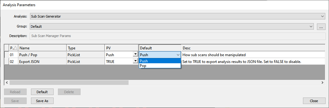
The Sub Scan Generator is a nSpec analyzer that manages target scans for queued analyses. It has one (useful) parameter - Push / Pop, which can be set to either Push or Pop.
This analyzer is meant to be strategically placed within an analysis group of other analyzers.
For the following sections, the following terms will be used:
Pushed/Virtual Scan: Scan created when sub scan generator is run in push mode, which is described in the following section.
Source Scan: Scan that was the target of the sub scan generator.
Target Scan: Scan that is the target on non-sub scan generator analyses.
Push Mode
When the Sub Scan Generator’s Push / Pop parameter is set to Push, the generator is in push mode.
In push mode, the behavior of the Sub Scan Generator is:
When run as a standalone analysis (not in an analysis group):
A new virtual scan ID is created in the scan’s database
A new virtual scan folder will be created in the scan’s folder
The new virtual scan’s ID will be the biggest scan’s ID + 1
The scan property
Pushed ScanIDwill be written into theScanPropertiestable for the source and virtual scans. The scan property’s value will be the virtual scan’s ID
When run in an analysis group
Everything that happens when the sub scan generator is run as a standalone analysis happens here
The target scan is the newly created virtual scan
Pop Mode
When the Sub Scan Generator’s Push / Pop parameter is set to Pop, the generator is in pop mode.
In pop mode, the behavior of the Sub Scan Generator is as follows:
Nothing happens when run as a standalone analysis (not in analysis group):
When run in an analysis group
The target scan is the source scan, no matter what a previous sub scan generator did in push mode