
Predictive Focus Algorithms
Overview
nSpec can automatically predict the surface of any given sample using predictive focus algorithms.
Predictive focus algorithms use the results of the autofocus phase of scanning to estimate the focal plane of the given sample. There are a number of different predictive focus algorithms that can be used to predict and model a sample’s surface topology.
Predictive focus algorithms can be configured and set in the Autofocus Settings dialog, located in Imaging Settings. Users must select Automatic Predictive for Autofocus Type in order to choose a Predictive Focus Algorithm.
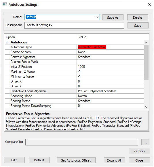
Note that when selecting either the PreFoc Kriging, PreFoc Polynomial Advanced, or PreFoc Planar Advanced algorithms, after selecting the algorithm, users must save the settings in order to see the additional parameter settings appear in the settings dialog.
Autofocus Background
The following diagram gives an overview of how the autofocus phase of scanning works, along with its inputs and outputs. This article will go into detail about the various surface predictor algorithms that can be used as inputs to the autofocus step.
Surface Prediction Algorithms
The six available algorithms are as follows:
PreFoc Polynomial Standard
PreFoc Polynomial Advanced
PreFoc 3CP
PreFoc Triangular Standard
PreFoc Planar Advanced
PreFoc Kriging
In general, using the PreFoc Polynomial Standard option is recommended. If the surface prediction result using this algorithm is not adequate, e.g. does not suffieciently capture or model the sample surface, we recommend using the PreFoc Kriging option instead.
See the table below for more information on what each algorithm is ideal for. Some focus point patterns are incompatible with certain surface prediction algorithms.
Surface Prediction Algorithm | Use Cases | Algorithm Description |
|---|---|---|
PreFoc Polynomial Standard | For general use cases, we recommend this option, which has a fast runtime. Should only be used with a rectangular grid of focus points, which makes it ideal for device scans. | Creates a model of the surface that goes through all focus points, using a polynomial algorithm. Creates a continuous, curved surface. |
PreFoc Polynomial Advanced | Flexible option with many configurable parameters, can be used with irregular focus point pattern, and will cover the edges of a circular wafer especially at higher magnification. More details on the PreFoc Polynomial Advanced algorithm parameters below. | Creates a model of the surface using a polynomial algorithm. Creates a continuous, curved surface. |
PreFoc 3CP | Can be used for irregular, non-square patterns. | Creates a model of the surface using the 3 closest focus points to calculate the Z value of a given point. Creates a non-continuous surface |
PreFoc Triangular Standard | Ideal for low magnification and smooth surfaces. Very fast, easy to configure. Can be used with an irregular focus point pattern. | Creates a multi-plane, non-continuous model of the surface using the 3 focus points that comprise the smallest perimeter triangle around a given point. |
PreFoc Planar Advanced | Can be used with irregular focus point pattern, but should only be used if the sample is known to be a plane. | Creates a single plane model of the surface by calculating a best fit plane through the focus points. There are two parameters: Number of fit attempts, and Objective Depth of Field, which will throw out outlier focus points when calculating the best fit according to a given tolerance. |
PreFoc Kriging | Good for irregular surfaces with nonsquare patterns of many (16+) focus points. Prefer over PreFoc Polynomial Advanced because it is generally faster and more accurate, and covers a similar use case. More details on the PreFoc Kriging algorithm parameters below. | Generates an continuous surface from the focus point z-values, using statistical modeling of all points to make an estimation of the Z value at a given point. |
PreFoc Kriging Parameters
Kriging is a procedure that generates a continuous surface from a set of known focus point z-values. It uses statistical modeling to make an estimation of the Z value at a given point, using some or all of the given z-values, where points closer to the point of interest are more heavily weighted than those further away.
Recommended Settings
We recommend starting with the follow settings and modifying as necessary.
Use Constant for Model Type parameter
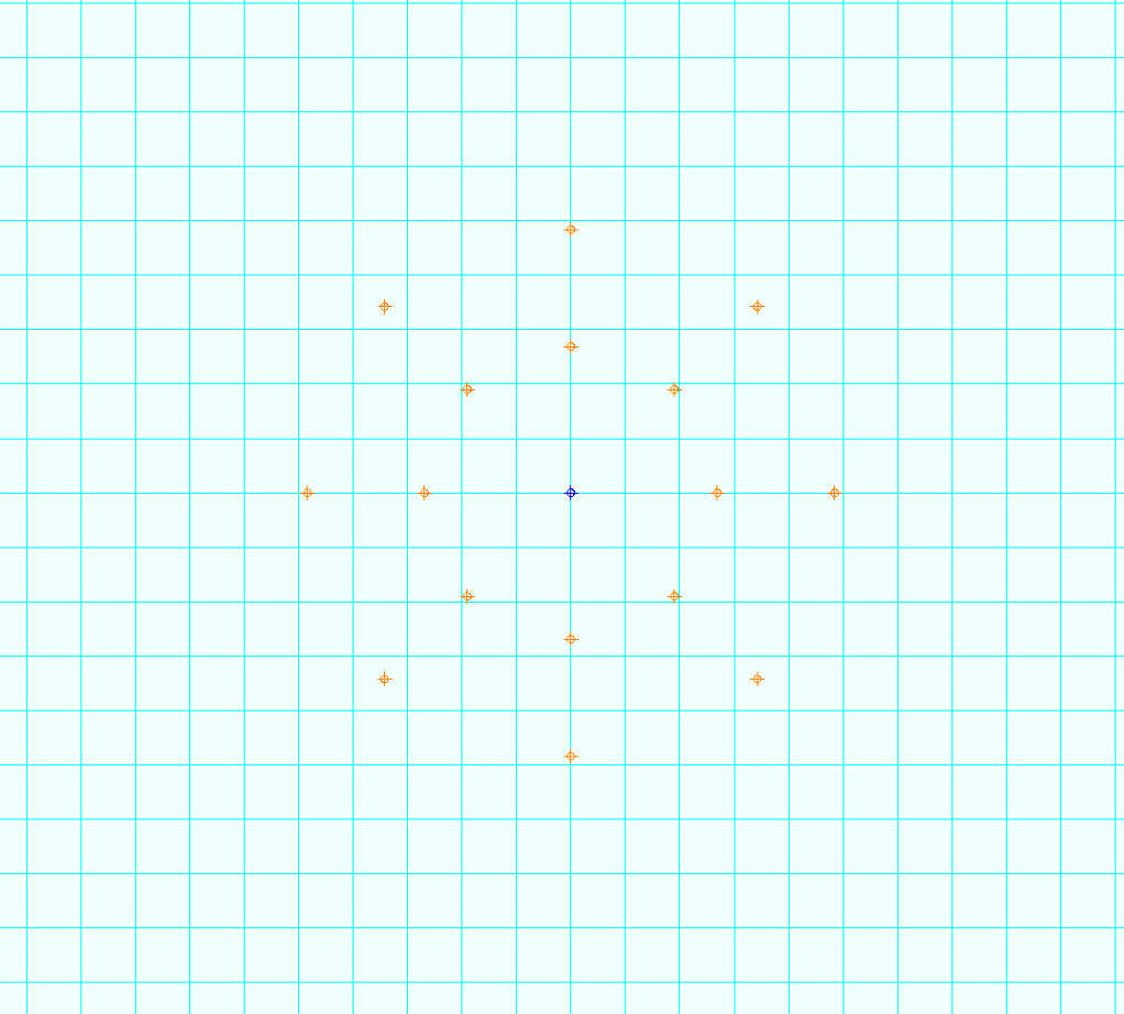
Use a 16 point circular predictive focus pattern with 2 rings and 1 center point
Outer ring of 10 points should be near edge of the wafer
Middle ring of 5 points should be halfway between the center point and outer ring
No phase between rings
PreFoc Kriging Parameter Descriptions
Parameter Name | Parameter Values | Description |
|---|---|---|
Krige Type | Simple, Ordinary | Simple is recommended, relates to an assumption about the mean of the focus points. |
Model Type | Constant, Linear, Spherical, Exponential, Gaussian, Power | Type of equation to fit through the focus points. Will relate how the neighboring points influence the estimated z-value at a given point. |
Neighboring Points | Number, 1 up to number of focus points. | The number of neighboring points to use when estimating the z-value for a given point. |
Range | Number, up to the diameter of the sample. | Specifies the distance from a point of interest to consider as influential to that point of interest. Points outside of this boundary will influence the estimated z-value much less. Usually a large value. |
Sill | Number | This number is the variance in z-values for points outside of the range. Should not be used with the Power model type, instead set when using the Exponential model type parameter. |
Exponent | Number | If using the Power model type, this parameter sets the degree of the exponent. |
PreFoc Polynomial Advanced Parameters
PreFoc Kriging is preferred over PreFoc Polynomial Advanced for the same use case, as it is more accurate. However, if you’d like to experiment using the PreFoc Polynomial Advanced surface prediction algorithm, feel free to tweak the following parameters.
PreFoc Polynomial Advanced Parameters Description
Parameter Name | Parameter Range | Description |
|---|---|---|
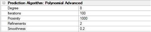
Degree | 2 to 15 | This is the polynomial degree, e.g. 2 is quadratic, 3 is cubic, etc. This is the parameter that controls the behavior of the whole algorithm and should be adjusted first. The degree is the number of undulations in one linear direction across the wafer. For example, a bowl shaped wafer, which is pretty common due to suction, will need degree 2: down and then up undulation. Odd degrees will create non-symmetric undulations and should be avoided but may work in some cases. |
Refinements | 0 to 3 | The number of times the algorithm subdivides the surface in between the focus points for greater detail. Choosing 1 will divide the surface in half, 2 will divide in quarters, and so on. The greater the number of refinements, the slower the algorithm. This can be experimented with for fine adjustment, 1-3 is ideal. |
Iterations | 0 to 1000 | After refinement, the final surface is fit. This is the number of iterations the algorithm will perform to adjust the fitted surface numerically. This parameter value can go up to a 1000 in steps of 100. This can be experimented with for fine adjustment. |
Proximity | 0 to 1000 | This parameter determines how close the surface passes through the focus points. 1000 means the surface passes exactly through the focus points, and 10 or 100 means approximately. This is a weight so is independent of distance. |
Smoothness | 0 to 1 | This is a constraint on how smooth the final surface should be during fitting. It is a scalar value between 0 and 1, where 1 is a very smooth/flat plane. This value can be decreased with the use of a lot of focus points, but if very few focus points are used with a high degree, smoothness can be increased to guarantee a more natural surface. |