
High Resolution Mosaic Generator
Overview
Currently, the post-scan mosaic generated by nSpec is a low resolution copy of what appears on the nSpec - Stage View after a scan. The High Resolution Mosaic Generator (HRMG) allows users to generate flawless, perfectly stitched, and up to full resolution mosaics matching the input scan pixel resolution.
The most common use cases for HRMG are:
Saving a single high quality continuous image of wafer samples for manual defect inspection
Removing gaps between image tiles caused by optical aberration
Generating image sets for the Virtual Device Inspection (VDI) workflow
The High Resolution Mosaic Generator is disabled by default. If you would like to use this feature and it is not currently enabled, reach out to mailto:support@nanotronics.ai for assistance to activate.
Usage
The HRMG is highly flexible, and accepts an overlapped nSpec scan, then outputs a mosaic or image set depending on the runtime configuration. The most basic output generates a full-resolution mosaic of a wafer scan without any image registration. In this scenario, the algorithm simply positions the input image tiles adjacent to each other. Inputting an overlapped scan to the HRMG is more useful, as the HRMG will perform stitching registration calculations between all of the image tiles. This means there will be no discontinuities across the high resolution image output, under nominal input conditions.
The job property percentOverlap can be assigned to any job to produce an overlapped scan. For the HRMG, a value of 15% is recommended.
The following matrix describes supported input scan types:
Scan Type | Requires Device Layout | Output | Supported? |
|---|---|---|---|
Wafer | - | High-res Image | Yes |
Aligned Wafer | - | High-res Image | Yes |
Aligned Wafer | Yes | Device Scan* (VDI Workflow) | Yes |
Device | Yes | High-res Image | Yes |
User-Defined | - | High-Res Image | No |
*Notice that if the input wafer is aligned and a device layout is provided as an input to the HRMG parameters, the output is not a single mosaic image but rather a Device Type Scan. This is called the Virtual Device Inspection workflow, and is a sepa
Parameters
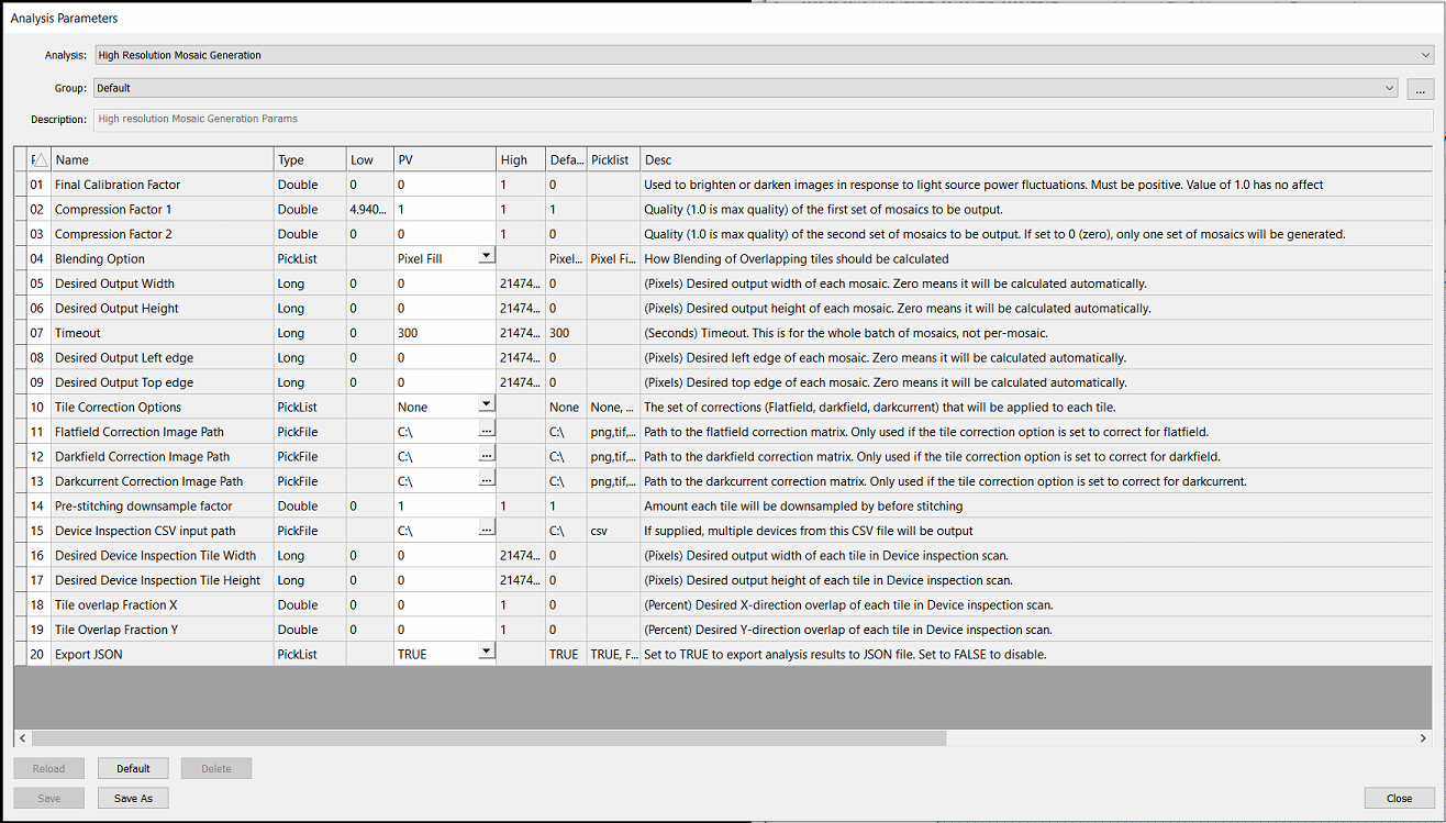
There are many parameters for this analysis, but for the most part these can be left as default values. The table below provides descriptions and notes on the HRMG parameters.
Parameter | Description | Note |
|---|---|---|
Final Calibration Factor | Used to brighten or darken images in response to light source power fluctuations. Must be positive. Value of 1.0 has no affect | Recommend ignoring this parameter unless instructed by Technical Service team. This parameter interacts with other features. |
Compression Factor 1 | Quality (1.0 is max quality) of the first set of mosaics to be output. |
Important! High Resolution Mosaics can only save to disk if small enough to comply with Windows and TIF image format constraints. Compression must be small enough to generate an image < 4GB If the mosaic is larger than this, the Mosaic Generator will silently fail and reports as complete in the exception log even though no mosaic is output |
Compression Factor 2 | Quality (1.0 is max quality) of the second set of mosaics to be output. If set to 0 (zero), only one set of mosaics will be generated. | |
Blending Option | How Blending of Overlapping tiles should be calculated (Pixel Fill, Gradient Mask) | For smoother blends, Gradient Mask is recommended. |
Desired Output Width | (Pixels) Desired output width of each mosaic. Zero means it will be calculated automatically. | Setting this will override compression factors. |
Desired Output Height | (Pixels) Desired output height of each mosaic. Zero means it will be calculated automatically. | Setting this will override compression factors. |
Timeout | (Seconds) Timeout. This is for the whole batch of mosaics, not per-mosaic. | |
Desired Output Left edge | (Pixels) Desired left edge of each mosaic. Zero means it will be calculated automatically. | Recommend setting to 0. |
Desired Output Top edge | (Pixels) Desired top edge of each mosaic. Zero means it will be calculated automatically. | Recommend setting to 0. |
Tile Correction Options | The set of corrections (Flatfield, darkfield, darkcurrent) that will be applied to each tile. | Recommend setting to None and using global system flatfield correction (FFC). |
Flatfield Correction Image Path | Path to the flatfield correction matrix. Only used if the tile correction option is set to correct for flatfield. | See above |
Darkfield Correction Image Path | Path to the darkfield correction matrix. Only used if the tile correction option is set to correct for darkfield. | See above |
Darkcurrent Correction Image Path | Path to the darkcurrent correction matrix. Only used if the tile correction option is set to correct for darkcurrent. | See above |
Pre-stitching downsample factor | Amount each tile will be downsampled by before stitching | Recommend stitching at full resolution (1.0) |
Device Inspection CSV input path | If supplied, multiple devices from this CSV file will be output | *See Virtual Device Inspection workflow for details on this format |
Desired Device Inspection Tile Width | (Pixels) Desired output width of each tile in Device inspection scan. | Recommend outputting image tiles that match the input tile width (ex: 4096px by 4096px for systems with a Bonito Camera with standard configuration |
Desired Device Inspection Tile Height | (Pixels) Desired output height of each tile in Device inspection scan. | See above |
Tile overlap Fraction X | (Percent) Desired X-direction overlap of each tile in Device inspection scan. | Recommend setting to 0 |
Tile Overlap Fraction Y | (Percent) Desired Y-direction overlap of each tile in Device inspection scan. | Recommend setting to 0 |
Export JSON | Set to TRUE to export analysis results to JSON file. Set to FALSE to disable. |