Create North-South-Origin Alignment
North-South-Origin alignment uses a north, south, and origin point to align the camera to a patterned sample during scanning. Setting up an image setting group and autofocus are prerequisites to setting up alignment.
Navigate to the Device Inspection Alignment wizard via nScan - Full Stage View > Scan > Device Inspection Alignment > Start Wizard…
Choosing Alignment Points
In this dialog, you will select three points on the wafer to align the camera and layout file to the sample’s pattern – a north point, south point, and origin point. nSpec uses a cross-correlation based algorithm to match the chosen alignment points to the sample.
The north and south points chosen are ideally unique structures on the wafer that are directly north and south of each other. If there are no unique structures on the wafer, the structure chosen needs to be unique within a single field of view.
This sample has been loaded manually with the flat oriented towards west. The flat can be oriented towards any cardinal direction: north, east, south, or west.
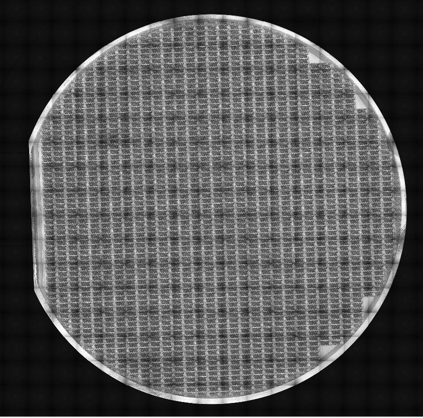
Looking at a 2x scan of the wafer below, we can see that there are no unique fiducial markings on this wafer. However, there are unique structures that we can choose as our north and south alignment points.
There are two pairs of unique features on the wafer that could be potentially be used for our north and south alignment points. Either set of north-south pairs could be used, however, north point option 1 and south point option 1 are a more optimal pair than north point option 2 and south point option 2, because there is more distance between the option 1 pair than the option 2 pair.
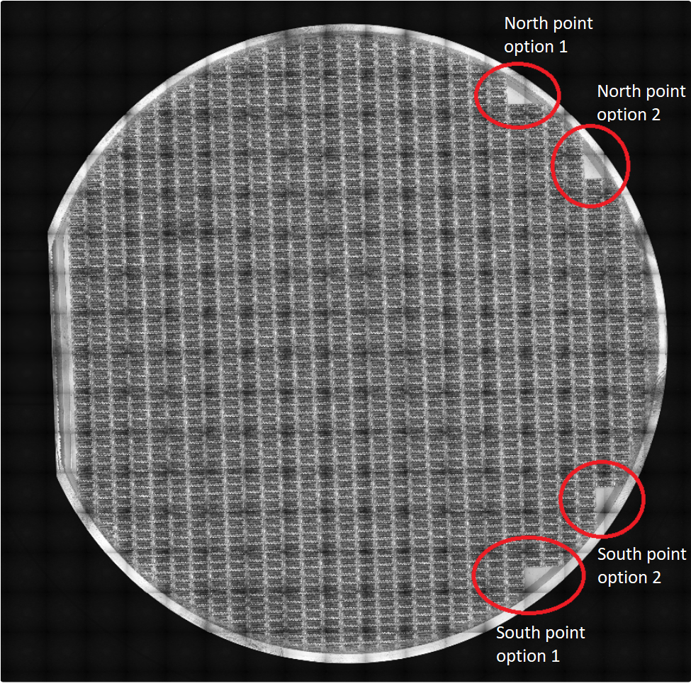
Looking closer at north point option 1, we will choose the corner of the bare portion as the center of our alignment point.
Define North
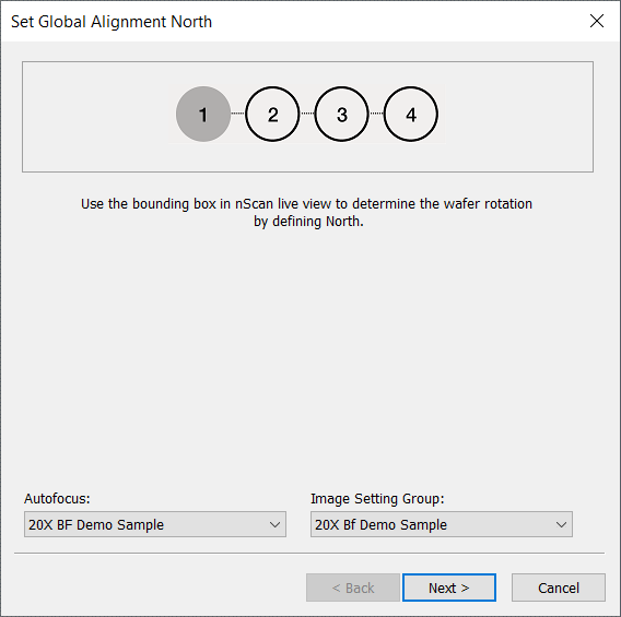
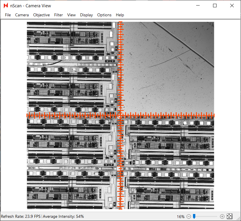
Once the alignment dialog is open, point to your autofocus settings and image setting group. Before continuing on and clicking Next, you must define “North” on your wafer, which is defined by drawing a bounding box in the nScan - Camera View window.
For best results, we performed the following steps to draw the bounding box.
Click the expand to fit button in the bottom right corner of the Camera View.
Click and drag a bounding box centered on the corner of the blank area as the center. We recommend that bounding boxes should be roughly 1/4 the size of the field of view.
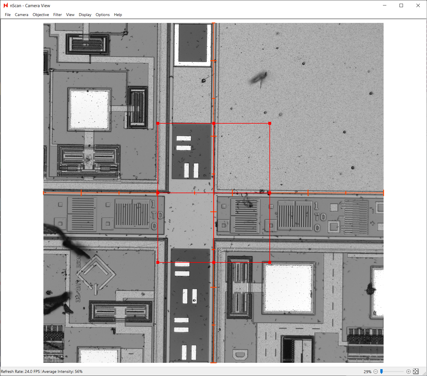
Zoom in to make sure that the bounding box is truly centered. Correct if necessary.
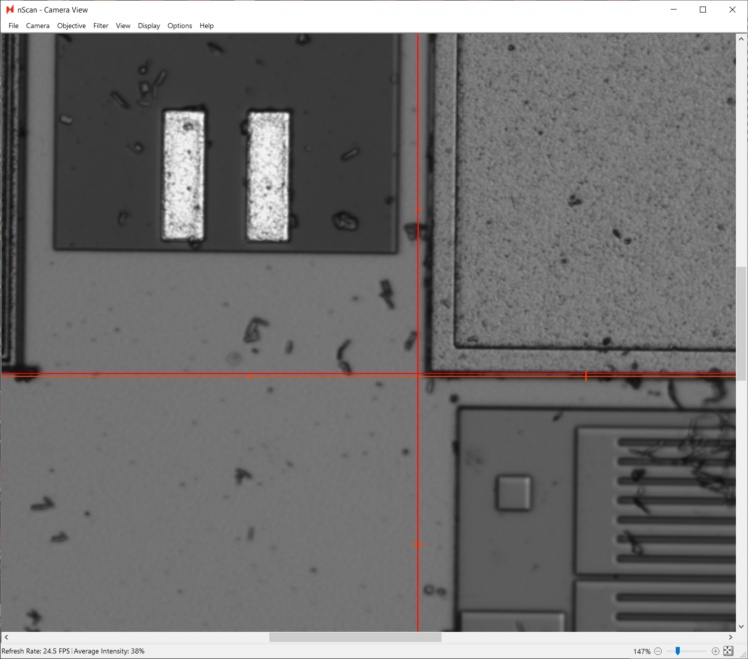
The center of the bounding box was not perfected aligned to the corner in the screenshot above, and has been corrected in the screenshot below.
Now that the north alignment point is defined, click Next.
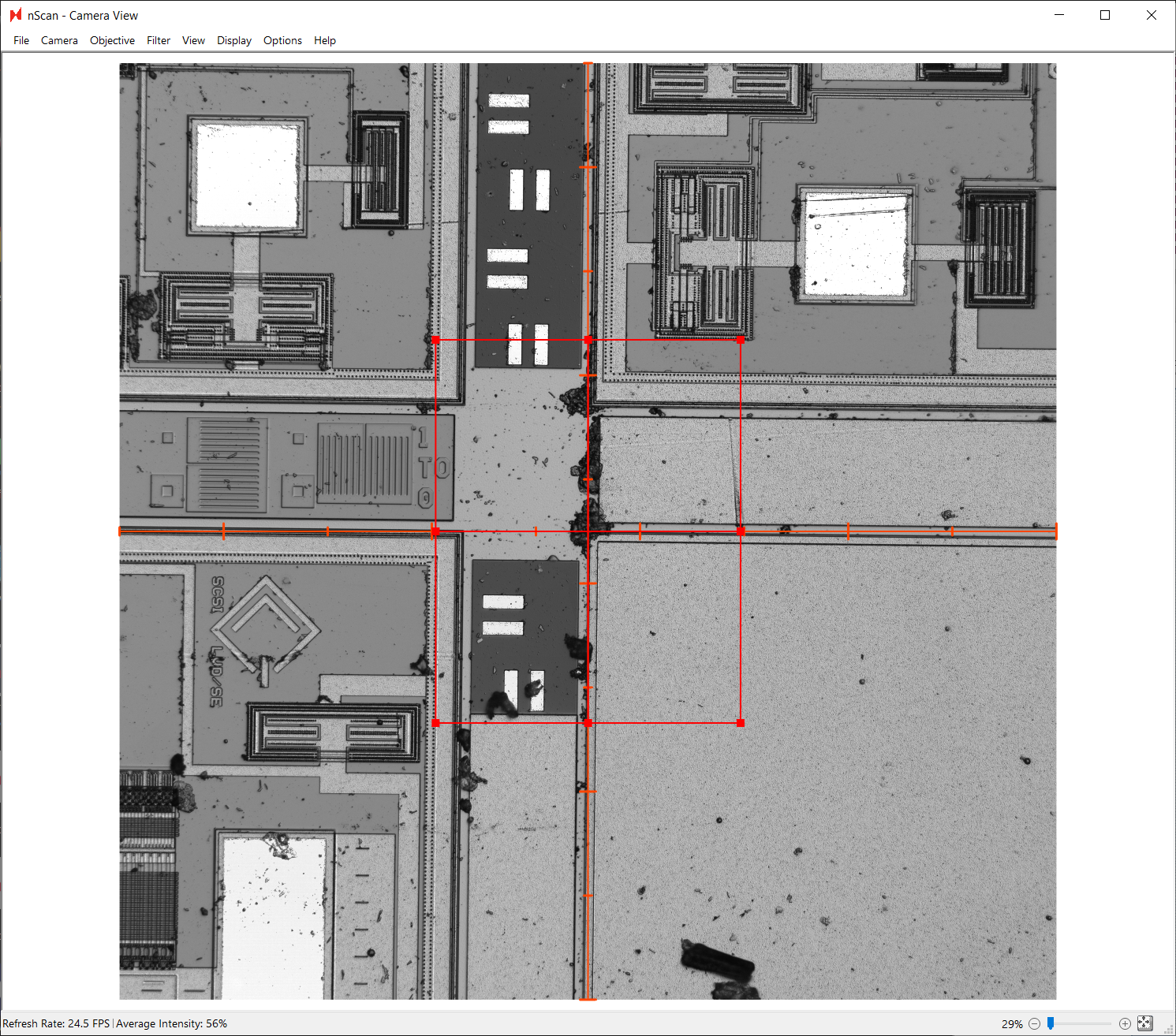
Define South
Next, we will define the south point. Again, we will set the autofocus and image setting group to the settings created before.
We highly recommend using the bounding box drawn to define the north alignment point to capture the south alignment point. Additionally, we recommend using the joystick or down arrow key to navigate towards the south point.
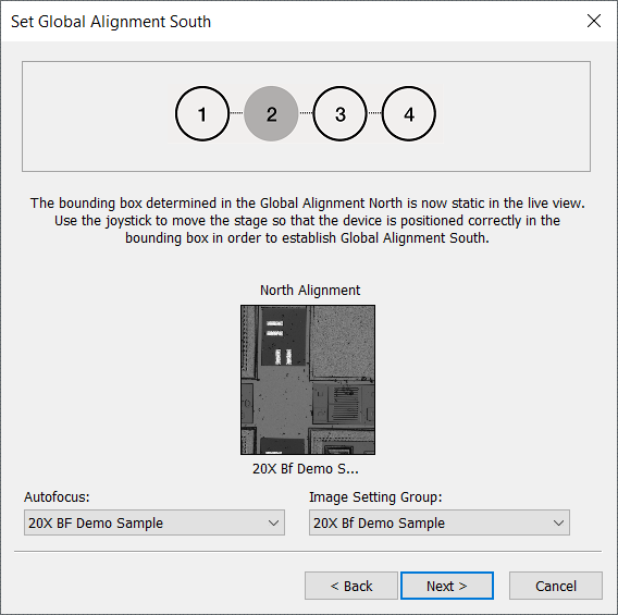
Here, we are choosing the corresponding unique structure, directly south of the chosen north alignment point. Click Next.
Define Origin
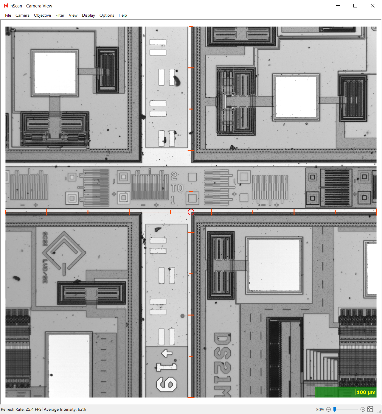
Lastly, we will define the origin, which defines the (0,0) coordinate of the wafer.
Any point can be defined as the origin, and we will choose a point close to the wafer center as our origin point. The center of the stage is roughly 102,000 by 102,000 µm. Because this sample was carefully placed in the center of the stage, we can assume the wafer center is near the stage’s 102,000 µm, 102,000 µm point. We will temporarily switch to a lower magnification objective to aid in finding the center point.
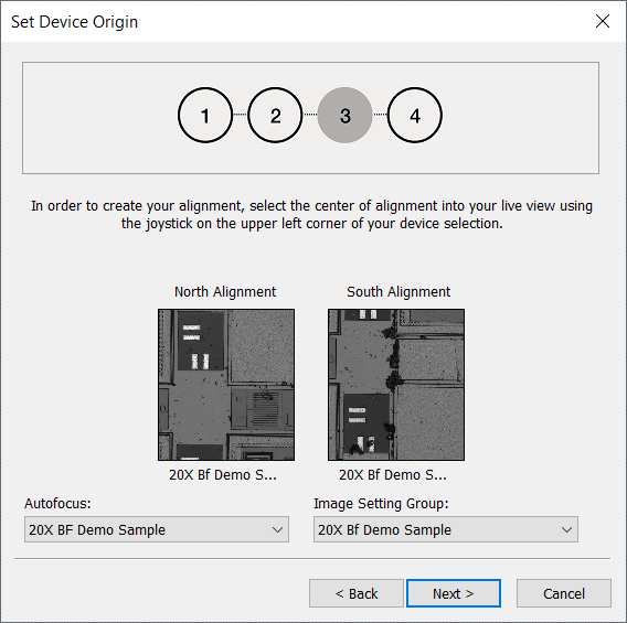
Once we’ve arrived at the central intersection of this patterned wafer, we will select the top-left corner of the device closest to the wafer center as the origin point. Again, we will set the autofocus and image setting group settings. Click Next.
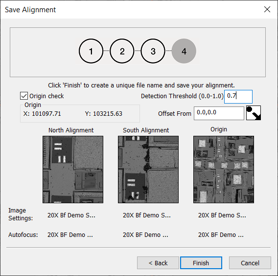
Finishing Alignment
The final step in creating the alignment file is to set the Detection Threshold to 0.7. A higher threshold fine--tunes the fiducial detection algorithm to be more conservative.
Click Finish. A dialog to save the alignment as a CSV file will appear. We will name ours “Demo Wafer Alignment.csv”.