
nSpec v0.21.1.0 External Release Notes
nSpec Version 0.21.1.0
Release Date:
Documentation Updated:
Major Features: GDS Masking, Configurable Light Tower, Bare Wafer Alignment for Device Inspection
Overview
This version includes many features that didn’t quite make it into v21.0.0 after many months of release candidate cycle testing held up that build. As a result, there are a large spread of features and functionality in this build that while they weren’t necessarily tied to urgent deliverables, were deemed to be valuable for customer release by the product team.
Upgrading to v0.21.1.0
Required Library Update
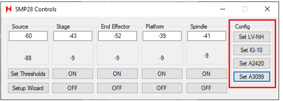
Autoloader 2s with a Generation 3 prealigner assembly (P/N: 3099) will need to have their Arduinos flashed by the latest TSToolKit software. This is in addition to the flash required for generation 3 aligner lasers. The exlog will show these values during initialization. The program option as of v0.21.1.0:
For aligner lasers:
Gen2 do not need to be flashed (nSpec already assumes LV-NH)
Gen3 need to be flashed with IG-10
For prealigners:
Gen2 do not need to be flashed (nSpec already assumes A2420)
Gen3 need to be flashed with A3099
Autoloader 2s with a Generation 3 prealigner will perform an automatic search for its starting position, which will now be written to the exlog.
The default Device Inspection parameter - Golden Template Processing Batch Size - has been updated to -1. The process value of this parameter is not affected when upgrading. -1 is now recommended.
For tools with a bonito camera, the recommended value for Frame Refresh Limit (FPS) is -1 (free run mode) and the recommended value for Camera Acquisition Frame Rate Limit (Frames Per Second) is -1 (free run mode). If you experience performance issues with nSpec when using these values, you may set hard limits to these options.
Major Enhancements
GDS Masking
Overview
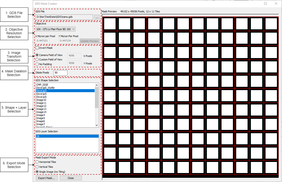
nSpec now has a built-in utility for creating device inspection masks for Calma GDSII files - the GDS Mask Creator. This utility is accessible from Main View / Stage View → Utility → GDS Mask Creator….
Interface
Control | Description | Usage |
|---|---|---|
GDS File Selection | Sets a compatible Calma GDSII file | Select file used to create device layout |
Objective Resolution Selection | Sets X/Y Micron per Pixel | Select objective used when creating device scan |
Image Transform Selection | Color inverts and pads the entire image. | Select Camera Field of View |
Mask Dilation Selection | Increases the number of pixels surrounding a shape’s layer | 0 is fine, but can be increased for more coverage |
Shape + Layer Selection | Sets shape and layer to mask | Select shape (and appropriate layer(s)) used to create device layout |
Export Mode Selection | Sets the mask export mode | See Workflow below |
Mask Preview | Shows what the exported mask will look like when exported |
|
Workflows
The GDS Mask Creator can be used to create classic device masks (mask linked to device templates) and custom masks. Scans that include >100 template files must use the Classic Device Masks Workflow.
Classic Device Masks Workflow (Export Mode = Horizontal/Vertical Tiles)
A large mask can be sliced into individual masks during export by selecting the Horizontal Tiles or Vertical Tiles export modes before exporting. When set to Horizontal Tiles, the mask is sliced based off the horizontal movement of the stage during a device scan. When set to Vertical Tiles, the mask is sliced based off the vertical movement of the stage during a device scan. The export mode should be chosen based on the type of scan being run:
Scan Type | Export Mode |
|---|---|
Continuous Scan | Horizontal Tiles |
Stop & Go scan with the program option Path Optimization = 0 | Horizontal Tiles |
Stop & Go scan with the program option Path Optimization = 1 | Vertical Tiles |
After clicking Export Mask… in the GDS Mask Creator, you must set the mask’s filename as your target template’s filename. For example, if your target template is nano_demo_0001_template.png, then your mask’s filename should be nano_demo.png. After exporting, you may overwrite your template’s mask(s). Warning: If you export into the directory containing your target template, there will be no prompt to confirm overwrite of existing masks.
Custom Device Masks Workflow (Export Mode = Single Image (no Tiling))
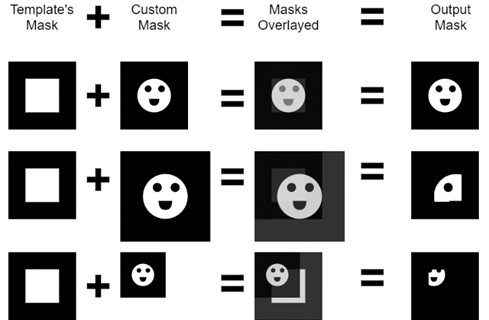
A new parameter has been added to the Device Inspection analyzer - Custom Device Mask; masks exported with the Single Image (no Tiling) export mode (using this workflow) will be specified using this parameter. Custom masks are used in addition to template masks. Specifically, custom masks are template masks are combined, before image analysis, to create an output mask. An output mask is created with the following method:
The custom mask is sliced depending on the number of template masks
If a template is only one image, then the custom mask is not sliced
If a template has n images, the custom mask will be sliced into n individual custom masks, where each individual custom mask lines up with its corresponding template mask
Each custom mask and template mask are lined up top-left corner to top-left corner
Each output pixel is the result of a logical AND operation between the template and custom masks’ pixels
Output pixels can only be white if both the pixel from the custom mask and the template mask are white. If either pixel is black (or both are black), the output pixel is black
Each output mask is cropped to the dimensions of the template mask
Bare Wafer Alignment - Dual Flat Support
In version 0.21.0.0 we enabled Bare Wafer Alignment - a new type of scan alignment that intelligently detects where the wafer sits on the stage, identifies the wafer flat or notch, and then aligns the scan with the alignment feature positioned at one of the cardinal positions. This update adds support for dual flats.
Autoloader Alignment Improvements
A number of autoloader alignment improvements have gone into this build. In general, the autoloader should be more stable when wafer notches are placed onto the pre-aligner with slight offsets.
Camera Performance & Stability Improvements
This body of work sets the stage for higher throughput scanning.
New Features
Highlights
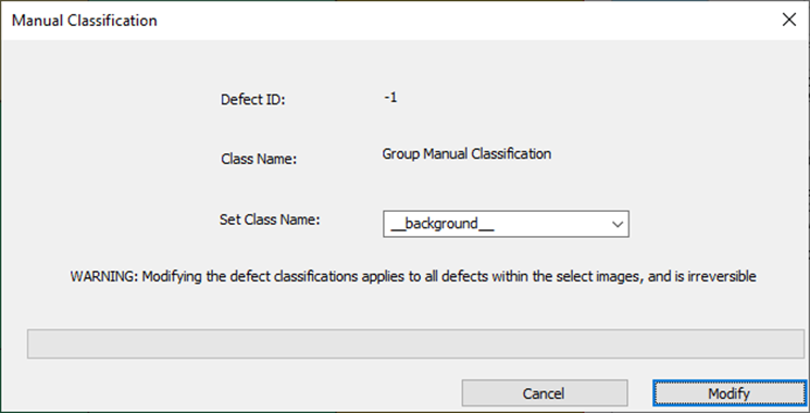
Manual Defect Classification Correction Support
Users can now manually reclassify defects in nView.
Note, for Group Classification Changes, there is a known issue where attempting to open the dialog over a remote session (i.e. via TeamViewer) is difficult.
Running Single Classification Change (Single Tile view in nView):
Shift + M while moving mouse (to open dialog) to change a single defect classification name to any classification name in the drop down (Drop down is based off all defect classes that were present in the model at time of analysis).

Running Group Classification Change (Multi Tile view in nView):
In nView’s Mosaic view, before clicking and dragging across multiple tiles, hold down M button to open dialog.
This will change all the defects in those tiles to the class name chosen in the drop down
Configurable Light Tower Support
nSpec systems with the light tower assembly can be configured by specifying a LightTowerConfig.yml file inside nSpec’s ProgramData/ConfigFiles directory. Each individual light on the light tower can now blink, remain on, or remain off when a specific nSpec action is performed. Specifically, the following actions are available for configuration:
State | Trigger Action |
|---|---|
ERROR_STATE | Job/scan fails |
BUSY_STATE | Job/scan is running |
FREE_STATE | The system is not in any other state |
UNLOADING_STATE | Job/scan is finished |
CALIBRATION_STATE | nScan is initializing |
The following lights are available for configuration:
Light | Note |
|---|---|
RED |
|
YELLOW |
|
GREEN |
|
BLUE | Only available on 4/5-color light towers |
WHITE | Only available on 5-color light towers |
ALARM | Not a light, but a sound |
The following light states are available per light:
Enumeration | Descrirption |
|---|---|
-1 | State of the light will not change |
0 | Light will be off |
1 | Light will be solid on |
2 | Light will be blinking on and off |
The following light states are available per light:
Enumeration | Descrirption |
|---|---|
-1 | State of the light will not change |
0 | Light will be off |
1 | Light will be solid on |
2 | Light will be blinking on and off |
For example, an example action configuration can be the following:
ERROR_STATE:
    RED: 0
    YELLOW: 1
    GREEN: 0
    BLUE: 0
    WHITE: -1
    ALARM: -1
Sample configurations can be found in this Jira’s attachments: NSPEC-4545
Dual-Flat Bare Wafer Alignment Support
The Bare Wafer Alignment Wizard now presents three new different types of fiducial arrangements:
Dual Flat (180° offset)
Dual Flat (90° offset)
Dual Flat (45° or 135° offset)
When any of these options, nScan will use the longer of the two edges when determining the main edge (and consequently, the alignment angle).
Device Inspection on Bare Wafer Support
Device Inspection functionality has been upgraded to support device inspection analysis for bare wafers.
The
Bare Wafer Alignment Wizard now has a field for origin offset, which can be used to specify a wafer’s origin with respect to the wafer’s calculated center in aligned coordinates (NSPEC-5413).
Device Inspection scan’s now accept
Bare Wafer Alignment (.json) files in addition to Classic Device Inspection Alignments (NSPEC-5329)
Basic Selection analyses will now automatically analyze defects within the device boundaries (
NSPEC-5361 adds device boundary detection functionality and NSPEC-5551 makes functionality automatic for device scans).
SECS/GEM Upgrades:
nSpec has introduced several upgrades to its SECS/GEM interface including the following:
JIRA ID | Description |
|---|---|
OCR ID is now always sent back to GEM host | |
Events and variables added to indicate wafer positions as they navigate across the cassette, aligner, and stage | |
Event added to indicate end of scanning; when nSpec is ready to accept more commands |
General Improvements
JIRA ID | Description |
|---|---|
NSPEC-4461 | nSpec’s with an interlock system now enforce that the enclosure is locked during nScan initialization |
NSPEC-4862 | Device IDs are now overlayed onto devices in the Device Layout dialog |
NSPEC-5241 | Hardware initialization updated to allow parallel loading of independent hardware items |
NSPEC-5426 | “Advanced” options are now hidden in Bare Wafer Alignment Wizard |
NSPEC-5570 | Fixed a bug where nSpec would crash when trying to view a deleted analysis group |
NSPEC-5571 | Fixed a bug where nInstall would leave a ‘jobs.dbb’ file in ProgramData |
Scanning Improvements
JIRA ID | Description |
|---|---|
NSPEC-5251 | Updated image capture code to greatly improve overall scanning and live view performance |
NSPEC-4550 | UseInitialZ job property now properly prevents the overwrite of the autofocus group’s specified offset |
NSPEC-5194 | Fixed a bug where video sweep would run on the RTX6000 and cause focus to fail |
NSPEC-5274 | Camera Acquisition Frame Rate Limit (Frames Per Second) program option can be set to free run mode (-1) (SEE Upgrading SECTION) |
Analysis Improvements
JIRA ID | Description |
|---|---|
NSPEC-5550 | Device Inspection analysis performance for large datasets is greatly improved with update to Golden Template Batch Size functionality |
NSPEC-4333 | Destination folders for golden templates can now be created automatically |
NSPEC-4406 | Gen3 AI analysis performance for large datasets is greatly improved |
NSPEC-4669 | Database write times for defects is greatly improved |
NSPEC-5058 | Fixed a bug where Gen4 analysis would hang on the last image |
NSPEC-5387 | Fixed a bug where defects found with the Gen4 AI analysis would render at an incorrect orientation |
NSPEC-5415 | Default value for Golden Template Processing Batch Size has been updated to -1 (automatically determine batch size) |
Autoloader Improvements
JIRA ID | Description |
|---|---|
Notch detection algorithm greatly improved to accommodate off-center aligner placement | |
Aligner type is now autodetected (SEE Upgrading SECTION) |