
nSpec v0.21.0.0 External Release Notes
nSpec Version 0.21.0.0
Release Date:
Documentation Updated:
Major Features: Bare Wafer Alignment, GDS Layout Creation
Overview
Upgrading to v0.21.0.0
Required Library Update
To get the latest installer to upgrade to v0.21.0.0, please contact Nanotronics Technical Support at support@nanotronics.co.
During the upgrade process, please review the following adjustments that may need to be changed to perform a smooth upgrade:
Autoloader Laser Amplifier Sensor
Important for all nSpec PS systems
nSpec v0.21.0.0 treats the autoloader laser amplifier settings differently than before if an IG-010 Keyence sensor is present in the autoloader. It is very important for safe wafer alignment to update the following settings on the alignment laser module if an IG-010 Keyence sensor is present. Additionally, the sensor will have to be flashed using the TStoolkit (WhatScopeDoIHave).
On the laser amplifier sensor hardware (located inside the autoloader near the aligner), set the following:
AnH = 0
AnL = 10
Note: The AnH and AnL settings are reversed compared to previous versions of nSpec.
Then, within nSpec, update the following:
Program Options > Autoloader > Invert Aligner Sensor Readings set to "0"
For additional instruction on how to safely update these settings, please reach out to Nanotronics technical service at support@nanotronics.co
Live View Frame Rate
Within nSpec Program Options, under Camera settings, set GenICam Acquisition Frame Rate Limit to 30 fps. By default, this new parameter is set to 60 fps, however this value needs to be lowered, especially for newer Bonita cameras that capture very large images. Additionally, in Live View settings, set Frame Refresh Limit (FPS) to -1. This will instruct the live view to capture images as fast as the camera allows.
Precision Scan Automatic Lighting
To run precision scans with any form of auto-light adjustment (masked or unmasked), as of v0.21.0.0 you must now verify that the Auto checkbox in the job’s image group settings is checked for the light you want to adjust.
Major Enhancements
Bare Wafer Alignment
Overview
nSpec supports alignment of bare wafers. The Bare Wafer Alignment uses an automatic fiducial detection algorithm to find the angle of any wafer, bare or patterned, relative to the stage. The alignment file generated using the Bare Wafer Alignment Wizard is an optional, but highly recommend input to the Scan Settings dialog.
Enabling Bare Wafer Alignment in Scan Settings
The Alignments field for Wafer patterns in the Scan Settings dialog can accept both Device Inspection Alignment files (.csv) and Bare Wafer Alignment files (.json).
Alignment will be enabled if this field has a valid alignment file.
Alignment will be disabled if this field is left blank.

Alignments field in Scan Settings Dialog
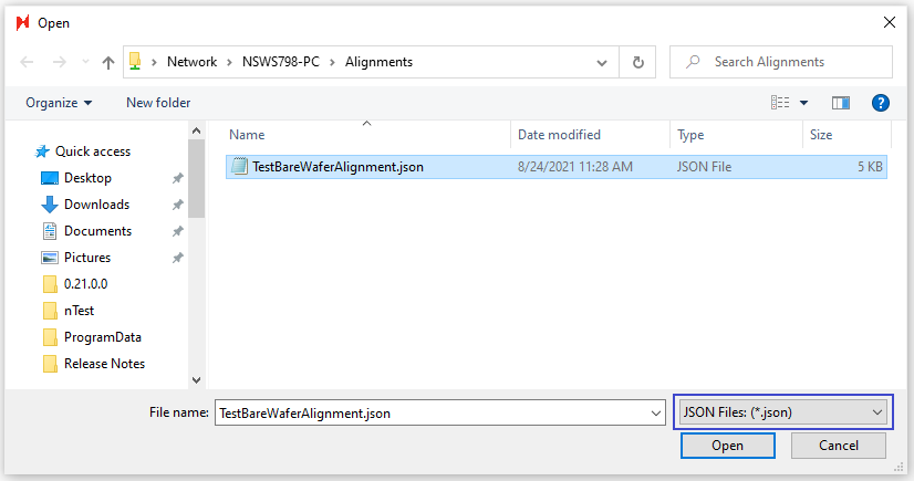
Bare Wafer Alignment (JSON) file selection
Prerequisites for Creating a Bare Wafer Alignment File
Prior to creating a Bare Wafer Alignment file, do the following:
Place a representative wafer on the stage.
Create an image settings group with low magnification (i.e., 1x, 2.5x, or 5x should all work).
Create an autofocus group with Use F-stop set to 0.
Navigate to the wafer’s fiducial (i.e., flat’s corner or notch) so that it is centered in the live view.
Creating a Bare Wafer Alignment File
To create a Bare Wafer Alignment file, navigate to the Bare Wafer Alignment Wizard through Stage View > Scan > Bare Wafer Alignment > Wizard.
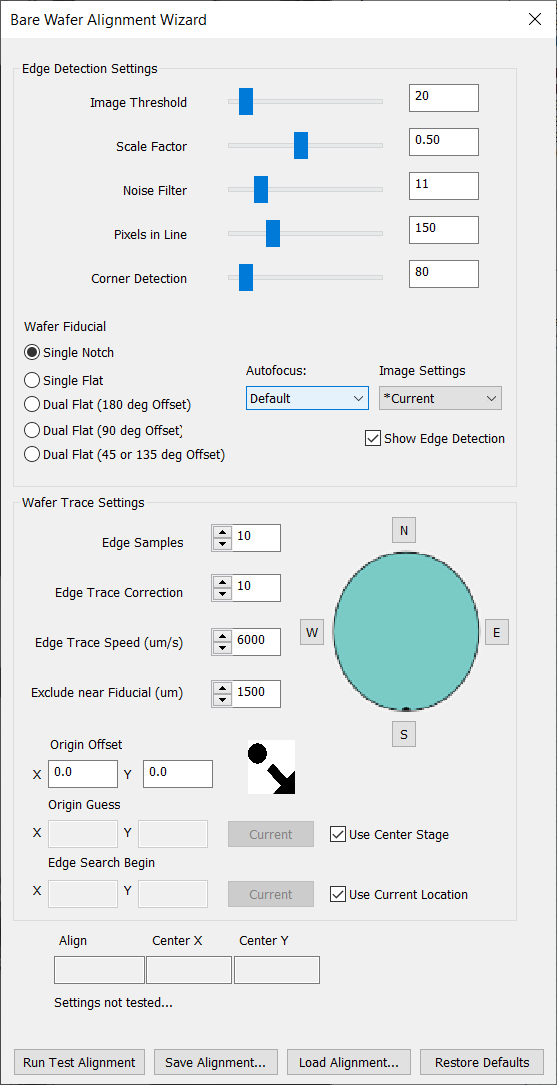
The Bare Wafer Alignment Wizard will appear, and the live view will automatically have Edge Detection enabled. When enabled, Edge Detection will display the following highlights in the live view:
Color | Description |
|---|---|
Gray | Wafer area |
Black | Stage area |
Green | Wafer edge |
Blue | Other contours |
Yellow | Cross indicates detection of a fiducial’s corner |
Red | Indicates how lines are detected |

The goal of this alignment setup is to optimize the settings in the Bare Wafer Alignment Wizard so that only the corners of the target fiducial have yellow crosses on them. You can then click Run Test Alignment to test the assigned settings. Once satisfied, you can click Save Alignment… to save the alignment.
Bare Wafer Alignment Wizard Settings
Edge Detection Settings
Setting | Description | Recommendation |
|---|---|---|
Image Threshold | Determines which part of the image is wafer vs stage. | 20 is usually good. |
Scale Factor | Determines scaling of the image for processing. | Lower is faster but can create reduce precision. |
Noise Filter | Applies a blur filter to reduce noise. | Use this and Smoothing to remove excess contours and make sure the edge of the |
Pixels in Line | The number of pixels used to find the line. | If the fiducial isn’t being found reliably, lower this value. |
Corner Detection | The distance allowed for the corner detected to be from the edge. | Keep as low as possible. |
Minimum Angle | The minimum angle between red lines that identifies a corner. | For notch wafers, 35° is usually a good choice. |
Autofocus | Autofocus group to use when alignment starts. | |
Image Settings | Image settings to use during alignment. |
Wafer Trace Settings
Setting | Description | Recommendation |
Edge Samples | Number of samples to take along | More will be more accurate but slower. |
Edge Trace Correction | Angle the stage movement takes when moving to the next sample. | Adjusting this can help track the edge better. |
Edge Trace Speed (µm) | Distance the trace will move at each stage instruction. | Lower will be slower, but more reliable. For nSpec systems with higher FPS, this can be higher. |
Exclude near Fiducial (µm) | Distance a point must be from the fiducial to be used for center | Increase if the fiducial is being included in edge calculations. |
Origin Offset (µm) | Applies an offset to the origin point defined in a layout file. | |
Origin Guess (µm) | Origin guess is the expected sample center. | Setting this parameter is helpful if nSpec has trouble finding the sample on the stage at the start of the alignment process. |
Edge Search Begin (µm) | nSpec will begin searching for the edge of the wafer to begin bare wafer alignment at this position. | Setting this parameter is helpful if nSpec has trouble finding the sample on the stage at the start of the alignment process. |
Wafer Alignment | Four buttons N, S, E, W for selecting where the fiducial is supposed to be aligned. | Align angle result will be the rotation needed to align the wafer with that point. |
Measurements Taken During Bare Wafer Alignment
Certain wafer properties measured and calculated during Bare Wafer Alignment will be automatically written to the database. These property values can also be manually input as job properties, and manual inputs will overwrite the values obtained from running Bare Wafer Alignment in the database.
Running Bare Wafer Alignment will calculate and write the following values to the database.
Scan Property | Description |
|---|---|
SampleOrientationMarkType | Notes the wafer fiducial type, Notch or Flat. When using the autoloader and performing a bare wafer alignment, if a flat is not found, the scan property value is automatically determined to be a Notch. If Bare Wafer Alignment is not performed at all, the value is NA. |
OrientationMarkLocation | Notes the orientation of the wafer fiducial, North, South, East or West. If there is more than one orientation mark, this value will mark the orientation of the larger of the two orientation marks (e.g. if there are two flats, this value denotes the major flat location.) If in the rare case there are multiple marks of the same size, this value denotes the first mark found during alignment. |
WaferCenterX | X axis value that marks the center of the wafer, relative to the stage origin (top left corner). |
WaferCenterY | Y axis value that marks the center of the wafer, relative to the stage origin (top left corner). |
OrientationMarkLength
| Micron measurement of each flat. If there are multiple marks, the value written to the database will be a comma separated value of the mark lengths in descending length. |
WaferMeasuredDiameter | Micron measurement of sample’s diameter. Note: The diameter of the sample’s major axis is measured. |
GDS Layout Creation
Overview
nSpec supports nSpec device layout creation using Graphic Data System (GDS) files.
Steps to Import
To convert a GDSII file into an nSpec Layout file:
Create a Device Inspection Alignment where the origin is the location of the GDSII file’s origin
Go to Stage View → Create Device Layout
Click Alignment… and load your created alignment
Click Device Layout… (which will open a new Choose Layout File Type dialog)
Click GDS
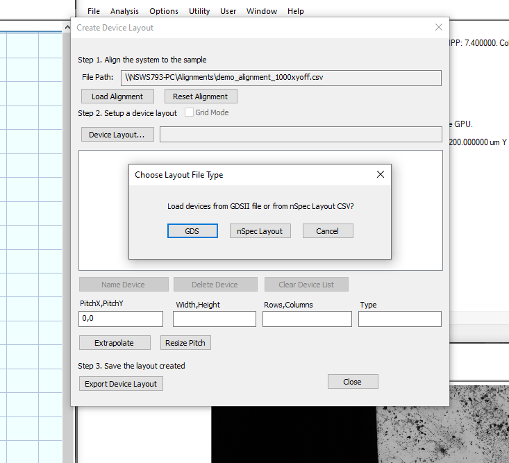
Chose the desired layer and click Import
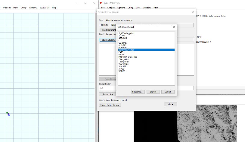
The device structure corresponding to the selected layer will be populated in the stage view and the device list, as if the devices where specified through extrapolation. At this point, the device layout the same as a traditional nSpec device layout.

New Features
Highlights
Manual Color Balancing:
Only relevant for nSpec systems with a color camera
nSpec now supports manual flat-field color balancing. To enable this option, set the Flat Field Correction Manual Color Balance program option under the Camera category to 1. When enabled, whenever calibrating objectives through Stage View → Calibrate → Calibrate Objectives, the following dialog will open:
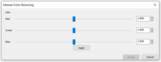
Within this dialog, the user can change the sliders for each color channel (Red, Green, and Blue for color cameras or Luminance for non-color cameras). Clicking Apply will cause flat field correction to happen, with the current slider values being applied to each channel. When correction has completed, the dialog will reopen. This allows the user to keep changing the balance until the desired effect is achieved. Once the desired balance has been found and applied, the user can select Accept to keep these changes. Otherwise, the user can click Cancel or end the dialog via the X button at the top and the system will run flat field calibration again with the color balance settings from when the first dialog was originally opened.
Air Knife Integration:
Hardware upgrade required, If you are interested in an Air Knife upgrade, please contact us at sales@nanotronics.co
nSpec can now clean Olympus turret objectives through the integration of the Air Knife hardware. To clean objectives using the Air Knife hardware:
Connect the Air Knife to an open USB port on the tool’s computer
Set Number of Objective Slots under Hardware: Turret Control to the number of physical objective slots available on the turret
Set Turret Switching Delay (ms) under Hardware: Turret Control equal to or more than the time it takes for one objective slot position to change
Start nSpec
Select Stage View → Utility → Clean Objectives
The Clean Objectives routine will do the following:
Move stage out of the way (so samples do not get shot with air/nitrogen)
Turn on air & nitrogen
Rotate nosepiece (turret) 1 full revolution (360 deg)
Turn off air & nitrogen
Return stage and objective to position before air knife job was started
Reporting Class View Settings:
Two new program options under the Reporting Class View category have been added to set the starting underlay and bin colors for class view reports: Default Underlay and Defect Bin Colors respectively. Furthermore, the first bin’s color is no longer a monochromatic gray.
Manual Set Z Focus Type:
A new autofocus type has been introduced: Manual Set. When selected, autofocus routines will simply set the stage’s Z position to the value specified in Initial Z Position in Autofocus Settings.
OCR Disable Scribe Reading Job Property:
Users can now enable/disable OCR scribe reads without changing the Autoloader program option via the job property: DisableOCR.
ManualLoadWafer Job Property:
The ManualLoadWafer job property now accepts two additional arguments: Z and Objective Slot. ManualLoadWafer can be used to set the state of the stage and turret after a job is finished.
The syntax for ManualLoadWafer is the following:
[X],[Y],[Z],[Slot #]
The following are possible arguments for the ManualLoadWafer job property:
Variable | Description |
|---|---|
X | Stage X position after job has finished |
Y | Stage Y position after job has finished |
Z | Stage Z position after job has finished |
Slot # | Target objective slot after job has finished (slots are defined in Camera View → Objective → Define Objectives |
The possible ManualLoadWafer job property combinations are as follows:
Variable | Description |
|---|---|
[X],[Y] | Sets stage X,Y position after job has finished |
[X],[Y],[Z] | Sets stage X,Y,Z position after job has finished |
[X],[Y],[Z],[Slot #] | Sets stage X,Y,Z position and objective slot after job has finished |
Analysis JSON Export Parameter:
Analyses that export JSON files now have a parameter to enable/disable JSON exports: Export JSON.
SECS/GEM Upgrades:
JIRA ID | Description |
|---|---|
NSPEC-4738 | Added event and variable for failed acknowledgements |
NSPEC-4737 | Updated handling of cassette scan command |
NSPEC-4711 | Added ability to run empty sample IDs |
NSPEC-4710 | Added debug logs to custom messages |
NSPEC-4649 | Added abort complete event |
NSPEC-4601 | Added ability to abort a scan based on read OCR scribe |
NSPEC-4466 | Added variable for alignment errors |
NSPEC-4647 | Updated ACKs for failed START_SCAN command |
NSPEC-4460 | Fixed bug where host would hand after an invalid job name was sent |
NSPEC-4404 | Added error handling for empty job name request |
NSPEC-4341 | Added ability to turn off all lights |
NSPEC-4340 | Added ability to set X,Y,Z stage position and objective slot |
NSPEC-4242 | Added ability to cancel queued analysis when STOP_JOB message is sent |
NSPEC-4822 | Added program option to enable/disable OCR read wafer ID alarms |
General Improvements
JIRA ID | Description |
|---|---|
NSPEC-5159 | Fixed a bug where auto light adjustment would not properly adjust light when using the Stage Calibration and Repeatability dialog |
NSPEC-4473 | GenTL errors during Bonito camera initialization are now printed in the exlog |
NSPEC-4589 | The Home and End keys on a keyboard now control the stage’s Z movement when |
NSPEC-4626 | User can now disable the GenICam Region of Interest program option |
NSPEC-4432 | Fixed a bug where autofocus would fail during a video sweep |
NSPEC-4223 | Fixed a bug where the live view selection tool (creates red box when pressing CTRL |
NSPEC-4743 | Increased Bonito cameras FPS to a maximum of 60 FPS (as of v0.21.0.0, 30 FPS is |
Scanning Improvements
JIRA ID | Description |
|---|---|
NSPEC-4734 | Improved throughput of flat-field image correction on Euresys capture card |
NSPEC-4651 | Improved path planning for Defect Review scans |
NSPEC-4687 | Tiles in a Wafer scan do not shift laterally when live view is minimized |
NSPEC-4624 | Tiles in a Device Inspection scan are not disconnected |
NSPEC-5153 | Precision scans on large devices are supported on nSpec systems with Bonito 2620 |
Analysis Improvements
JIRA ID | Description |
|---|---|
NSPEC-4357 | Moved Gen4 analysis connection issue logs from exlog to debug log |
NSPEC-4752 | Throughput of Device Inspection analysis running on GPU is improved |
NSPEC-4748 | Defect counts are properly calculated when edge exclusion is applied |
NSPEC-4669 | Database write times for defect exports are improved |
NSPEC-4609 | Fixed a bug where GPU with Padding > 0 would not do template alignment correctly for |
NSPEC-3768 | Fixed inconsistencies in defect count when masking for Gen3 AI analysis |
NSPEC-4485 | Fixed a bug where Device Inspection analysis would hang for very large device when run with GPU |
NSPEC-4431 | Fixed a bug where Gen4 analysis would disconnect in the middle of processing many images |
Autoloader Improvements
JIRA ID | Description |
|---|---|
NSPEC-5141 | Removed program option Invert Aligner Sensor Readings under Autoloader has been removed. Ensure your autoloader’s aligner laser settings AnL & AnH |
NSPEC-4496 | Fixed ability to use Map Sensor with original autoloader’s alignment algorithm |
NSPEC-4768 | Fixed sanity error due to unstable spinner alignment velocity |
NSPEC-4694 | Calibration dialog buttons Set Spinner Speed & Set Alignment Speed renamed to Set Spinner Alignment Speed & Set Spinner Find Speed respectively, which control database entries Spinner Alignment Speed & Spinner Notch/Flat Find Speed |
NSPEC-4603 | Added error handling to Autoloader 3’s Manual Control dialog |
NSPEC-4398 | Added OCR camera integration to Autoloader 3 |
NSPEC-4397 | Add option to use and switch between second load port in Autoloader 3 |
NSPEC-4462 | Added Quartet pre-aligners Integration to Autoloader 3 |
NSPEC-4399 | Added lift-pin chuck Integration into Autoloader 3’s stage load routine |